
Critical advances in re-engineering the cathode-electrolyte interface in alkali metal-oxygen batteries


Abstract
Due to its porous structure and special reaction characteristics, the cathode-electrolyte interface in alkali metal-oxygen batteries (AMOBs) has a substantial impact on their electrochemical performance. However, in traditional sandwich-like battery structures, the reaction position in the cathode is restricted to the finite planar cathode-electrolyte interface, leading to AMOBs with limited performance. As a result, a growing number of research studies have sought to re-engineer the cathode-electrolyte interface to enhance the performance of AMOBs. This review summarizes the latest methods published in recent years in this field and compares a variety of different techniques. Regardless of the method used, the ultimate goal is to expand the cathode-electrolyte interface to create more triple reaction activity sites for ions, oxygen and electrons. The most important performance improvement of AMOBs is reflected by the increased specific capacity. Additional challenges valuable for the further development of alkali metal-oxygen batteries are also discussed
Keywords
INTRODUCTION
In recent decades, the massive use of fossil fuels and electricity has greatly improved living standards worldwide. However, the use of fossil fuels, such as coal, oil and natural gas, is damaging our environment. Serious problems, such as global warming and air pollution, have made it clear that we must develop cleaner energy sources with improved specific capacity[1]. Alkali metal-oxygen batteries (AMOBs) have been widely studied as one of the most promising energy storage technologies due to their advantages, which include low costs and higher theoretical specific energy than lithium-ion batteries[2].
A sandwich structure of alkali metal (Li, Na or K)-electrolyte-cathode is widely used in traditional AMOBs[3-7]. Unlike other battery systems, the cathode of AMOBs can be viewed as either an open or semi-open structure because of the constant consumption and release of oxygen[8]. Taking the Li-O2 battery as an example, its electrochemistry can be expressed by the following reaction equation: 2Li + O2 ↔ Li2O2[9,10], where the important component of the cathode is the air diffusion layer that is responsible for electron conduction, gas diffusion and discharge product containment[2]. Carbon materials, such as Ketjenblack[11-13], are widely used to make cathodes because electrons can conduct at high speeds. In addition, some carbon materials, such as carbon nanotubes (CNTs)[14,15] and porous carbon foils[16], with loose porous structures allow oxygen to diffuse freely.
In order to improve the electrochemical performance of AMOBs, broad research activities have been proposed. However, most of these studies have focused on cathode catalyst exploration[17-20] and modification of the alkali metal anode and electrolytes[21-29]. It should be aware that the interface between the cathode and electrolyte also has a significant influence on the performance of an AMOB. In a conventional sandwich-structured cell, the electrolyte material is simply stacked with the air cathode. During the discharge process, the metal ions, as reactants, are only transferred to the surface of the cathode material[2]. Therefore, the reaction is limited to the plane where the cathode and electrolyte contact and the discharge products accumulate on this interface rather than filling the entire cathode structure[2,30], which results in reduced performance of the cell and a particularly low discharge/charge capacity. In the past five to ten years, there has been an increasing number of publications describing new methods for modifying the cathode-electrolyte interface. In this review, these novel approaches are summarized and discussed in detail.
APPROACHES FOR ENGINEERING THE CATHODE-ELECTROLYTE INTERFACE
Since AMOBs were proved to be feasible, improvements in the cathode-electrolyte interface have been continuous. In particular, in recent years, an increasing number of creative approaches have been proposed to improve the performance of batteries by modifying the interface[31-34]. Figure 1A shows the widely used sandwich structure in current alkali metal-O2 battery systems, where the alkali metal, electrolyte layer and cathode are simply stacked together. Therefore, there is large impedance in Li+, Na+ or K+ conduction and the reaction position of the battery is limited at the junction of the electrolyte layer and the cathode.
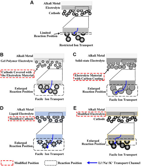
Figure 1. (A) Battery with sandwich structure. Schematic overview of four different approaches to engineer the electrolyte layer-cathode interface: (B) mixing electrolyte and cathode grains; (C) integration of electrolyte and cathode materials; (D) modification of cathode structure; and (E) modification of electrolyte.
To extend the reaction position, several methods have been demonstrated. These novel methods for the construction of cathode-electrolyte interfaces are schematically classified into four types, as summarized in Figure 1B-E. The first type of modification focuses on the sandwich structure battery, which is achieved by mixing gel polymer electrolyte and cathode materials. The electrolyte material is coated on the surface of the porous cathode to form three continuous channels of electrons, ions and O2 [Figure 1B]. In a classic example, Mushtaq et al.[31] mixed polymer precursors with CNTs as cathodes for lithium-oxygen batteries. The second type is to construct an integrated structure of the electrolyte and cathode. The electrolyte material is made into a porous structure as the cathode skeleton, allowing ions to conduct rapidly [Figure 1C]. Zhu et al.[33,35] published several works describing this integrated structure. The modification of the cathode structure [Figure 1D] and electrolyte [Figure 1E] generally involves modifying the materials[36-38] or redesigning their structures[39-41] to increase their contact area and therefore improve the capacity of the discharge products and prolong the battery life.
Mixing of cathode and electrolyte
In order to extend the contact interface between the electrolyte and cathode, the electrolyte and cathode materials can be mixed together. The ion transport channel (aprotic electrolyte or ionic liquid) is covered on the surface of the cathode material without damaging the cathodic porous structure. On this basis, the reaction interface is extended from a plane to the whole cathode, forming three continuous ion-electron-oxygen transmission channels.
A typical fabrication process for a composite cathode was designed by Mushtaq et al.[31] [Figure 2A]. A precursor slurry mix containing CNTs and modified silyl-terminated polyether (MSTP)-hexamethylphosphoramide (HMPA) was coated on carbon paper, which served as a cathode to assemble the cell[31]. Scanning electron microscopy (SEM) images of the CNTs before and after coating the mixed slurry were produced [Figure 2B and C]. It can be seen that the porous structure of the CNTs was maintained [Figure 2C]. The CNTs not only provided electronic transmission transport but also sufficient oxygen diffusion channels. HMPA can greatly improve the oxidation kinetics in the recharge process in the cells due to its ability to dissolve the discharge product Li2O2[31,42]. By comparing the composite cathode with an HMPA gradient (0, 5, 10 and 15 wt.% HMPA), it was found that the gradient with higher HMPA loading at the cathode showed a lower initial charge potential. Because the cathode materials could not be effectively polymerized when the mass of HMPA exceeded 15 wt.%, no higher concentration of experimental control groups was set. In addition, compared with the lithium-oxygen batteries (LOBs) based on the liquid electrolyte containing 15 wt.% HMPA, the polymer-based battery with MSTP-PE-HMPA-CNTs showed better performance and could operate for 120 cycles with charge potentials of < 4.05 V [Figure 2D]. The advantage of LOBs using polymer electrolytes can be explained by the unstable interface between the liquid electrolyte and Li anode[43].
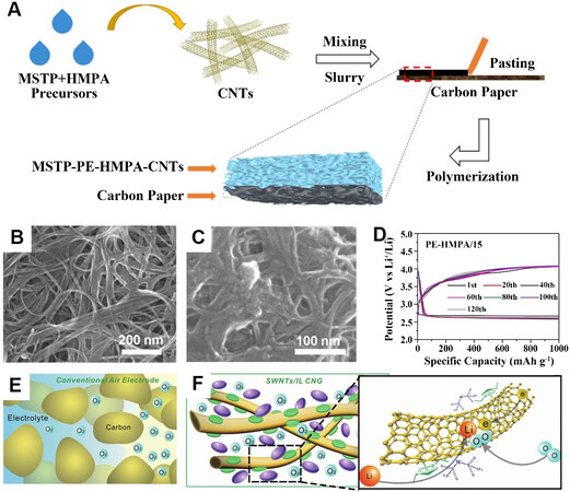
Figure 2. (A) Schematic diagram of MSTP-PE-HMPA-CNT composite cathode in situ fabricated by polymerization of the PE precursor. SEM images of CNTs (B) before and (C) after coating the slurry. (D) MSTP-PE-HMPA/15 for different cycles collected with a capacity of 1000 mAh g-1 at a current density of 200 mA g-1[31]. Reproduced from Ref.[31] with permission from American Chemical Society. (E) Three-phase interfacial reaction confined by the dissolved oxygen in a conventional LOB. (F) SWNT/[C2C1im] [NTf2] CNG. SWNTs (gold) were untangled by a π-cation/π-electron interaction with the imidazolium cation of [C2C1im]+ (green), thereby forming physical gels with cross-linked networks. The [NTf2]- ions (purple) were anchored in the gel through electric neutrality. Oxygen fills the entire CNG and electrons conduct along the CNTs. Lithium ions transfer from the ionic liquid electrolyte outside into the CNG[32]. Reproduced from Ref.[32] with permission from John Wiley and Sons. MSTP: Modified silyl-terminated polyether; PE: polymer electrolyte; HMPA: hexamethylphosphoramide; CNTs: carbon nanotubes; MSTP-PE-HMPA/15: the MSTP-PE-HMPA with 15 wt.% HMPA; LOB: lithium-oxygen battery; SWNTs: single-walled carbon nanotubes; IL: ionic liquid; CNG: cross-linked network gel.
Zhang et al.[32] designed a cross-linked network gel (CNG) consisting of single-walled carbon nanotubes (SWNTs) and an ionic liquid for the cathode of the LOBs. In the conventional structure of LOBs, as shown in Figure 2E, the three-phase interfacial reaction is confined by dissolved oxygen. The cross-linked network allows O2 to pass through rather than dissolve, so that the conventional three-phase electrochemical interface can be expanded into three-dimensional (3D) networks throughout the CNGs. The SWNTs were treated as electronic conductive passages, like other carbonaceous materials, and the support for the discharge products (Li2O2) due to their specific atomic structure and high electroconductivity. The ionic liquid covered on the surface of the SWNTs was responsible for the high conduction of lithium ions within the CNG. As shown in Figure 2F, the SWNTs were interlinked due to the specific role with ionic liquids by grounding into the imidazolium ion ionic liquid to form the gel. A discharge capacity of more than
The direct in situ preparation of gel polymer electrolytes (GPEs) in cells was demonstrated by Cho et al.[44]. The researchers injected materials, such as a poly(vinyl alcohol) (PVA)-containing liquid electrolyte, directly into cells and waited until it gelated. In contrast to the normal layered structure in which GPEs contact with the porous cathode directly, the new structure, where the gel was synthesized in situ, covers the surface of the porous cathode, as shown in Figure 3A. This approach greatly reduces the contact resistance and creates a channel where Li ions can conduct freely. In their report, three kinds of gel mechanism were introduced, namely, physical gelation, chemical polymerization of monomers and chemical cross-linking of polymers. Physical gelation was mainly achieved by tempering and dissolving PVA and then cooling it down. The addition of a thermal or photoinitiator to the gel matrix was the main method of monomer chemical polymerization. Thermal initiators were preferred for the in situ gelation of batteries. Photoinitiators were often added when the gelation was prepared under normal conditions. Gelation could also be achieved by adding special polymers to the liquid electrolyte, which provided additional mechanical toughness to the gel electrolyte. These methods, all of which in situ synthesized the gel in cells, provided additional insights into the integrated structure of the cathode and electrolyte.
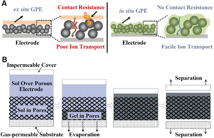
Figure 3. (A) Ex situ GPE vs. in situ GPE, with in situ GPE having higher ionic conductivity[44]. Reproduced from Ref.[44] with permission from John Wiley and Sons. (B) Schematic diagram of bottom-up infilling method[45]. Reproduced from Ref.[45] with permission from Springer Nature. GPE: Gel polymer electrolyte.
The following technique is an example of using the physical gelation method discussed above. Although their gelation was implemented in supercapacitors, this method could also be used to make the cathode-electrolyte integrated structure of LOBs. As above, Li et al.[45] made the gel by adding PVA to the electrolyte to heat it up, followed by dissolution and cooling. In particular, they proposed a new bottom-up method to fill gel electrolytes. Figure 3B shows the process of the experiment. The researchers added the electrolyte solution with PVA melted and cast on the porous electrode. Since the upper surface was covered with an impermeable film and the lower surface was in contact with a gas-permeable substrate, water vapor evaporated from the lower surface during the gelation process. The researchers compared it to the top-down infilling method. Through SEM measurements, it was found that the gel electrolyte could fill the entire electrode when the bottom-up filling method was used, while the other method could not achieve complete loading. EDS test results also proved this conclusion and it was attributed to the porous electrode structure that this method could be used for LOBs. This new gelation method also embodies the concept of modifying the cathode-electrolyte interface.
Physical gelation was also used to prepare a quasi-solid electrolyte for sodium-O2 batteries (SOBs).
Song et al.[47] used a novel electrolyte filling technology to produce supercapacitors with high volumetric capacitance and energy density. The process of the new electrolyte filling technology was illustrated [Figure 4A], where the electrolyte precursor containing a photoinitiator was coated on the surface of the porous CNTs. The GPE that was still able to flow completely penetrated into the pores inside the electrode due to gravity. Through irradiation with 365 nm ultraviolet light, the electrolyte was fixed to the surface of the electrode to achieve high ionic conductivity. This work provides new insights for LOBs (especially for those that use polymer electrolytes). LOBs require more ion-electron-oxygen interfaces. Polymer electrolytes and porous CNTs provide ion and electron transport channels. When using this method, the diffusion channel of oxygen should be guaranteed.
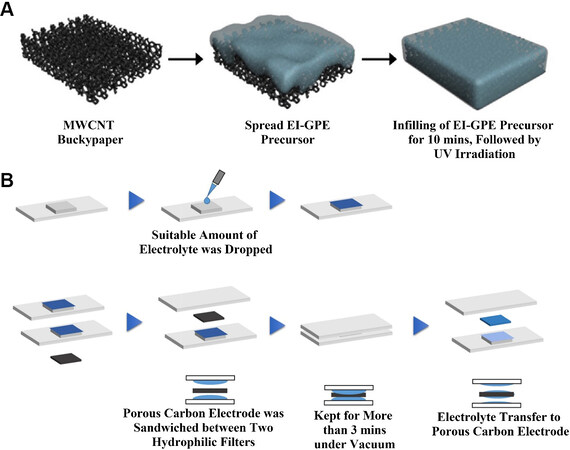
Figure 4. (A) Schematic illustrations for part of the preparation of EI-SC[47]. Reproduced from Ref.[47] with permission from Elsevier. (B) Schematic illustration of the stamping method[48]. Reproduced from Ref.[48] with permission from American Chemical Society. MWCNT: Multi-walled carbon nanotubes; EI-GPE: organic gel polymer electrolyte; EI-SC: flexible supercapacitor.
Inspired by the previous approach, the electrolyte filling technique was applied to the cathode preparation for LOBs by Matsuda et al.[48]. To create LOBs with higher energy density, the researchers compared three following methods, namely, the drop-casting, inkjet and stamping methods. The drop-casting and inkjet methods used micropipette and desktop jet-coating devices to impregnate the electrolyte onto the porous carbon electrode, respectively, and then kept it in a vacuum for a period of time. A schematic diagram of the third method is provided in Figure 4B. The electrode was obtained by sandwiching a porous carbon electrode between two hydrophilic filters impregnated with electrolyte and maintained in a vacuum. μXRF analysis was performed to determine the uniformity of the electrolyte distribution on the porous carbon electrode before the cell assembly. The results showed that the latter two methods are superior with regards to the comparison of the homogeneous electrolyte distribution. In electrochemical performance tests, a cell equipped with an electrode with an unevenly distributed electrolyte will exhibit greater polarization because the unevenly distributed electrolyte will result in fewer interfaces at which the effective reaction can take place. This interface is the cathode-electrolyte interface. Therefore, electrolyte filling technology is likely to become the focus of research on the performance improvement of batteries using porous electrodes. However, it is important to note that when using electrolyte filling to make the electrodes for LOBs, we need to preserve the oxygen channel instead of completely filling the porous cathode with electrolyte.
Inspired by the ion and nutrient transport in natural wood, Chen et al.[49] used natural balsa wood after chemical delignification and CNTs to create an F-wood-based LOB. The wood was treated with NaOH to remove lignin and hemicellulose and it retained excellent flexibility and high-speed ion transport channels. CNTs were coated onto the surface of the wood. Due to the interaction between them, some of the CNTs could be found in the internal channel of the wood using SEM. Nanoscale Ru treated as a catalyst for the oxygen reduction reaction (ORR) and oxygen evolution reaction (OER) was also loaded on the inner surface. The continuous three-channel structure extended the electrode-electrolyte interface and created a large number of active sites for the reaction to occur, thus enabling non-competitive transport of electrons, Li+ and O2. At a cutoff capacity of 1000 mAh g-1, the cell with the CNT/Ru-coated F-wood cathode displayed an overpotential of only 0.85 V at a low current density of 100 mA g-1 with a Coulomb efficiency of 82%. Even at a high current density of 1000 mA g-1, the overpotential remained relatively low at 1.14 V. As shown in Figure 5A, the researchers compared it with two other structures and found that it had the highest battery capacity (7300 mAh g-1). In addition, due to the excellent mechanical properties of the F-wood electrode, the Li-O2 cells were highly flexible and could even be bent or folded. This provided a new concept for the sustainable development of portable energy storage equipment.
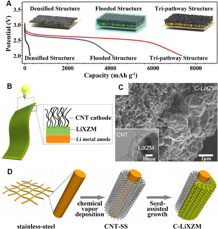
Figure 5. (A) Discharge curves of the initial cycle for three structures[49]. Reproduced from Ref.[49] with permission from John Wiley and Sons. (B) Schematic of the integrated C-LiXZM structure. (C) SEM image of C-LiXZM with a TEM image of the interface between the CNTs and LiXZM shown in the inset. (D) Schematic of the design and preparation of the integrated C-LiXZM[52]. Reproduced from Ref.[52] with permission from Springer Nature. CNT: Carbon nanotube; LiXZM: lithium-ion-exchanged zeolite X (LiX) zeolite membrane; CNT-SS: CNT grown in situ on stainless-steel; C-LiXZM: the integrated structure with cathode (CNT) and solid electrolyte (LiXZM); SEM: scanning electron microscope; TEM: transmission electron microscope.
A method of in situ synthesis of a GPE-electrode-integrated structure by monomer chemical polymerization was also reported[34]. The synthetic method of adding a photoinitiator is simple and effective and therefore particularly popular. A novel integrated cathode architecture was proposed by Xiao et al.[34]. Due to the GPE layer being sandwiched between lithium metal and cathode in traditional cells based on a polymer electrolyte, the GPE material cannot penetrate into the porous cathode, so that the three-phase interface (oxygen-GPE-cathode material) where the reaction takes place was restricted to the surface of the GPE. In the experiment, nanoscale Co3O4 was grown on the surface of a carbon cloth through the following reactions:


The prepared GPE was then infiltrated into the porous cathode through ultraviolet radiation, resulting in the formation of an integrated cathode of a Co3O4 nanoscale sheet array and gel polymer electrolyte. In the new integration architecture, the carbon cloth and small particles of Co3O4 were conducive to electron transport and Co3O4 was also a promising catalyst for the OER process[50,51]. The use of nanoarrays not only increased the surface area, but also provided a location for the deposition of discharge products. After testing, it was found that at the same current density, the capacity of the battery with the new structure was nearly double that with the traditional sandwich structure. Therefore, the performance was greatly improved.
In addition to using quasi-solid electrolytes, like GPE, as described above, composite structures with solid electrolytes have also been published. Chi et al.[52] proposed an all-solid LOB with a lithium ion-zeolite X (LiX) membrane, as schematically shown in Figure 5B. Figure 5D illustrates that CNTs-LiX zeolite membrane (C-LiXZM) was integrated by CNTs and the solid electrolyte membrane through an in situ assembly method. First, nitrogen-doped CNTs were chemical vapor deposited on a stainless steel mesh. After the hydrophilic treatment of the CNTs, the zeolite crystal seed slurry was coated on the hydrophilic side. The composite structure of CNTs and LiX was obtained through hydrothermal treatment and Li+ exchange. This strategy intelligently took advantage of the differences between the hydrophilic and hydrophobic properties of CNTs. The hydrophilic side of the CNTs was the basis for zeolite seed growth, while the hydrophobic side contacted with the outside atmosphere, as the transport channel of O2 and the storage space of the discharge product Li2O2. As an electrolyte layer, LiXZM is a typical solid electrolyte with the advantages of high Li+ conductivity and resistance to the growth of lithium dendrites. SEM and transmission electron microscope (TEM) images of the interface between the CNTs and LiXZM are indicated in Figure 5C. CNTs were uniformly distributed on the LIXZM surface without being destroyed. Under the same conditions, LOBs containing the C-LiXZM integrated structure worked for more than 149 cycles, much higher than for the non-integrated C|LiXZM structure, which ran for 86 cycles.
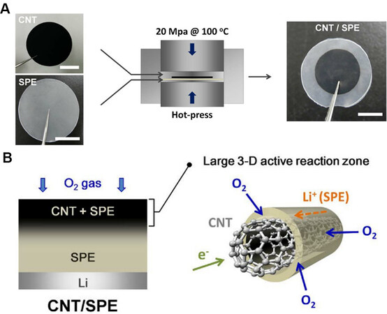
Bonnet-Mercier et al.[53] incorporated CNT electrodes into the solid polymer electrolyte (SPE) to reconstruct the interface between the electrolyte and cathode, resulting in a new design of 3D SPE structures for LOBs. Figure 6A indicates the preparation process of the 3D CNT/SPE. The SPE was soft penetrated into the CNT film with a 3D structure at a pressure of 20 MPa and a temperature of 100 °C. The final product of CNT/SPE consisted of a CNT core and a shell of SPE of tens of nanometers thick with SPE penetrated into the CNT electrode to a depth of ~30 μm. Simultaneously, the SPE coated along the surface of the 3D CNT electrode could maintain the gap in the CNT film, so the depth of oxygen diffusion and the storage space of the discharge products were also guaranteed. The 3D active reaction zone was found to largely extend [Figure 6B], so that LOBs based on CNT/SPE exhibited a higher capacity than the cells with a limited reaction area. Unfortunately, a reasonable discharge capacity and voltage curves were only shown during the initial cycle and serious side reactions were observed, which may be due to the decomposition of the SPE matrix prepared from poly(ethylene oxide) (PEO) upon cycling. Even so, this report provided a new development concept for the redesign of the electrode-electrolyte interface by coating the electrolyte on the surface of the cathode material to extend the interface.
Kitaura et al.[54] constructed a powdery composite electrode consisting of a solid electrolyte, an electrically conductive material and a nanoscale catalyst. CNTs played the roles of both fast electronic conductors and efficient reaction catalysts. A ceramic electrolyte (CE) was used to prepare the solid electrolyte due to its high ionic conductivity similar to LATP. An ethanol solution mixed with CE and CNT powders was added to the CE tablets and dried at room temperature to obtain the cathode-solid electrolyte composite structure. However, due to the poor stability of the CE toward the lithium anode, a polymer electrolyte layer was introduced between the lithium metal and the solid electrolyte, thus forming a lithium metal-polymer electrolyte-solid electrolyte-composite cathode battery structure [Figure 7A]. The impedance analysis of the battery showed that the interfacial resistance between lithium and the polymer represented almost all of the entire resistance of the solid-state battery. It was found that the first discharge capacity reached 400 mAh g-1 at a current density of 10 mA g-1. In addition, the different contents of CNTs also had a significant influence on the performance of the battery. The discharge capacity increased but the charge capacity decreased with increasing CNT weight ratio from 5% to 50%. According to the experimental analysis, solid-state batteries containing a 5% weight ratio of CNTs showed the best electrochemical performance.
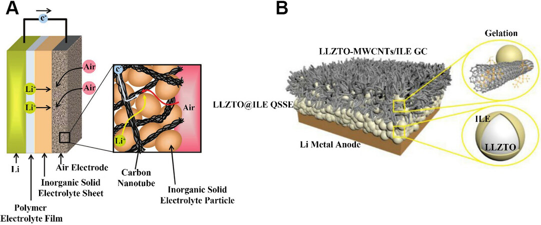
Figure 7. (A) Schematic diagram of a solid-state lithium-air battery using a lithium anode, a polymer electrolyte film, an inorganic solid electrolyte sheet and an air electrode composed of CNTs and solid electrolyte particles[54]. Reproduced from Ref.[54] with permission from John Wiley and Sons. (B) Schematic representation of the Li-O2 battery based on a MWCNTs-LLZTO/ILE gel cathode and LLZTO@ILE quasi-solid-state electrolyte[55]. Reproduced from Ref.[55]] with permission from Elsevier. ILE: Ionic liquid-based electrolytes; LLZTO: Li6.40La3Zr1.40Ta0.60O12; LLZTO@ILE QSSE: the ILE was solidified on LLZTO nanoparticles to construct quasi-solidstate electrolyte (QSSE); LLZTO-MWCNTs/ILE GC: the electrolyte was gelated by multi-wall carbon nanotubes (MWCNTs) to construct the gel cathode (GC).
Gao et al.[55] integrated a quasi-solid-state electrolyte (QSSE) with a gel cathode (GC) membrane by a simple roll-forming process. The QSSE was obtained by grinding a Li6.40La3Zr1.40Ta0.60O12 (LLZTO) powder and an ionic liquid electrolyte (ILE). The ionic liquid lost its fluidity after it was coated on the surface of the LLZTO nanoparticles, just as it solidified on the LLZTO, forming an egg-like structure. The LLZTO particles modified by the ILE provided a variety of pathways for Li+ transport. The difference between the GC and QSSE was the addition of a certain amount of multi-walled carbon nanotubes (MWCNTs). A schematic of the novel LOBs [Figure 7B] shows that the interconnected MWCNTs formed porous electron transport channels and that LLZTO particles were uniformly distributed throughout the GC. Before the assembly of the battery, the prepared QSSE and GC films were stacked together and then rolled into a film to achieve the integration of the cathode and electrolyte. They were then assembled together with the lithium metal. The interface between the electrolyte and cathode allowed the continuous passage of e-, Li+ and O2, which facilitated the electrochemical reaction. The battery showed good cycling performance at 60 °C, with an overpotential of 0.44 V and an efficiency of over 70% for over 70 cycles.
In general, this structure is suitable for solid and gel polymer electrolytes due to their poor fluidity. The modified composite structure requires only a thin electrolyte layer or even no electrolyte layer, because the ion transport channels are already part of the cathode.
Integration of cathode and electrolyte
A method using a porous electrolyte material as a cathode skeleton has been proposed[33,35,56]. The integration of the electrolyte and cathode means that they are not simply put together, but that they are all made of the same material, so the lithium ions can be transported quickly to the cathode to react. However, on the porous side of the electrolyte, an additional layer of electron transport channels is needed, which is usually carried out by the carbon coating.
Zhu et al.[35] designed a porous cathode based on a LATP material, where neither the electrolyte layer nor the cathode exist independently but instead form a whole. The solid electrolyte and cathode prepared with the same material were seamlessly connected through high temperature, which eliminated the large interfacial resistance in the traditional sandwich structure and was more conducive for lithium-ion transport. First, the porous cathode structure was formed with LATP powder and starch after pressing at high temperature. A layer of LATP film with a thickness of only 19 µm was then covered on a surface by slurry spin coating technology to form an integrated structure of porous cathode and dense electrolyte film. After the carbon coating, this structure enabled a continuous electron-ion-oxygen transport channel, which extended the three-phase reaction interfaces to the entire cathode. Figure 8A shows the structure with a three-phase transport channel. In addition, considering that impurities in the ambient air might enter the open system and react with the discharge products to form undesirable by-products, a 50 nm silicone oil film was introduced to the pore surface of the cathode as an oxygen selective membrane. The solid-state lithium-oxygen battery fitted with the new integrated structure achieved a capacity of 11697 mAh gcarbon-1 at a constant current density of 0.3 mA cm-2. In terms of cycling performance, 100 and 50 cycles were maintained at cutoff capacities of 1000 and 5000 mAh gcarbon-1, respectively.
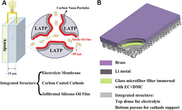
Figure 8. (A) Proposed solid-state LOB with an integrated structure of the solid-state LATP membrane, carbon-coated LATP cathode and a silicone oil film inside the cathode[35]. Reproduced from Ref.[35] with permission from Royal Society of Chemistry. (B) Schematic illustration of a novel LOB with an integrated solid-state electrolyte and cathode structure[33]. Reproduced from Ref.[33] with permission from Royal Society of Chemistry. LATP: Lithium aluminum titanium phosphate; EC: ethylene carbonate; DMC: dimethyl carbonate.
Zhu et al.[33] made further improvements to the above structure. A brass cover was tightly attached to the outside of the lithium metal, which acted as an anode current collector. A porous glass microfiber filter impregnated with liquid electrolyte was then sealed between the lithium metal and the LATP electrolyte, which was a simple physical isolation method to protect LATP from Li. On the surface of the porous cathode based on LATP, a second layer of carbon coating was added to form a bilayer carbon-coated cathode structure. The nano-carbon coating was formed by a 10% mass fraction sucrose solution. The structure of the new cell is shown in Figure 8B. In the assembled cells, the thickness of the LATP solid electrolyte layer decreased from 600 to 36 μm and the porosity of the solid cathode increased to 78%. The morphological evolution of the discharge products during discharge and charge was characterized by SEM. The results indicated that Li2O2 could be synthesized and decomposed normally. In terms of cycling performance, more than 100 cycles were achieved whether a 1000 or 5000 mAh g-1 cutoff capacity was used. In the course of 20 to 100 cycles, the polarization was not severe, which suggested excellent cycling performance of this new type of battery design.
Li et al.[56] reported a cathode-electrolyte assembly, where the solid electrolyte and porous cathode were prepared from the same material, Li1.5Al0.5Ge1.5P3O12 (LAGP). First, the LAGP powder was prepared by the traditional solid-state reaction method. A porous layer (cathode) and a dense layer (solid electrolyte) were then formed by pressing the powder mixture of LAGP, starch and pure LAGP powder at high temperature. Finally, a 10% mass fraction of sucrose solution was added to the porous layer at high temperature to form a carbon coating, which was used as a catalyst for LOBs. Through a schematic diagram of the LOB
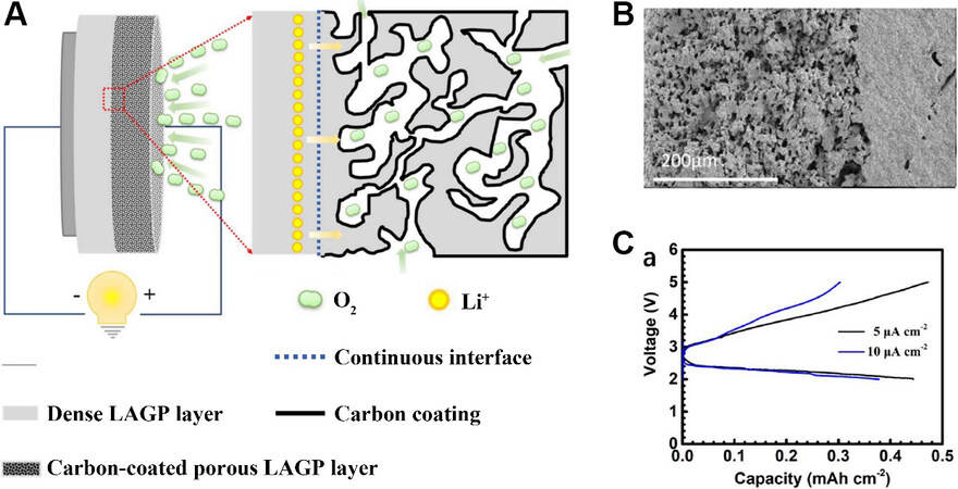
Figure 9. (A) Schematic diagram of LOB with integrated structure. (B) Cross section of structure. (C) Galvanostatic discharge and charge curves of the novel LOB, with currents of 5 and 10 μA cm-2 between 2 and 5 V[56]. Reproduced from Ref.[56] with permission from IOP Publishing. LAGP: Li1.5Al0.5Ge1.5P3O12.
This structure, which uses the same material to make the electrolyte and cathode skeleton, makes it possible to eliminate interfacial resistance. However, current research results show that the structure has only been used for all-solid-state AMOBs because the cathode skeleton requires good mechanical properties to support the discharge products.
Cathode modification
Researchers have improved the cathode-electrolyte interface by redesigning the cathode[39,49,53,57]. These modification methods generally include structural redesign and chemical composition improvements. This new structure is usually used in batteries containing liquid electrolytes. The sufficient contact between the fluid electrolyte and the modified cathode increases the number of active sites for reaction, thus enhancing the performance of the battery.
Kim et al.[41] proposed a structure consisting of an activated graphene-carbon aerogel (AGCA) coated with poly(pyrrole) (PPy) and used it as a cathode for LOBs. A schematic of the AGCA construction is shown in Figure 10A. This novel polymer cross-linked structure provides a channel for sufficient diffusion of oxygen and space for the storage of the discharge products. The solid cathode-liquid electrolyte interface was effectively expanded, which facilitated the rapid absorption and diffusion of oxygen. Moreover, the synergistic effect of the PPy catalytic layer and AGCA significantly improved the capacity and cycling performance of the battery. The carbon aerogel for batteries was prepared by solution gel polymerization and the PPy layer was formed on the surface of the AGCA by in situ electropolymerization. The PPy on the surface of the AGCA not only acted as a protective layer to prevent electrode degradation, but also promoted the cell reaction due to its electrocatalytic ability. The synergistic effect of the two materials greatly increased the number of electrochemically active reaction sites at the three-phase interface. Compared with the AGCA battery without a PPy catalyst, the PPy@AGCA battery showed a higher discharge voltage and a lower charge voltage, suggesting a significantly improved polarization in the charge and discharge process. This indicates that PPy could serve as a bifunctional catalyst of the ORR and OER for LOBs. Compared to the initial discharge capacity of batteries with and without PPy, a high discharge capacity of 5250 mAh g-1 was achieved at a constant current density of 200 mA g-1, which was 1.5 times that of the battery without PPy. The excellent reversibility of the battery was also evidenced by the almost complete decomposition of the discharge products.
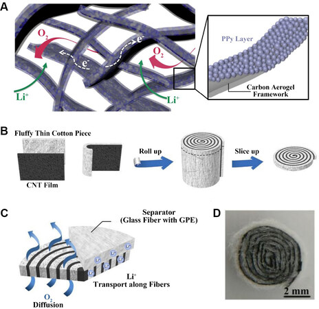
Figure 10. (A) Schematic illustration of 3D cross-linked structure of PPy@AGCA[41]. Reproduced from Ref.[41] with permission from RSC Pub. (B) Schematic diagrams of fabrication process of rolled CNT cathode. (C) Free diffusion channels of O2 and Li+[39]. (D) Product photograph of rolled CNT cathode[39]. Reproduced from Ref.[39] with permission from Royal Society of Chemistry. PPy: Polypyrrole; PPy@AGCA: PPy-coated activated graphene-carbon aerogel.
Huang et al.[39] proposed a rolled CNT membrane structure as a cathode for lithium-oxygen batteries. The raw materials used in the experiment were a CNT film and a thin cotton sheet. A schematic diagram of the preparation of the roll structure is shown in Figure 10B. Two bonded materials were rolled up and sliced thinly along a circular cross section. To ensure that Li ions can participate in the reaction successfully, 15 μL of GPE precursor solution was dropped onto the sheet. After heating, the partially wetted flakes became a gelatinized state, but the porous cathode structure did not change and the diffusion of oxygen was not hindered. In addition, the side reaction was inhibited by avoiding the contact between the discharge products and CNTs. It could be seen that both oxygen and lithium ions were able to diffuse along these transport channels [Figure 10C]. A photograph of the rolled CNT cathode is shown in Figure 10D. According to the SEM image, the discharge products covered on the surface of the porous CNT network after discharging and disappear after charging, in good agreement with the X-ray diffraction results. The battery with this structure achieved a discharge capacity of 13564 mAh g-1. During the first 50 cycles of the battery operation, there was minimal change in the over-charge and over-discharge potentials. After 150 cycles, the overpotential began to increase but was still maintained for more than 260 cycles.
Gilmore et al.[58] designed a novel cathode structure for K-O2 cells. The adjustment to the traditional sandwich structure was that a PPy layer was added between the porous cathode and the electrolyte layer. The PPy layer not only prevented O2 from diffusing into the electrolyte during battery operation, but also enhanced the discharge performance and consumption of oxygen in the cathode. The cathode materials were divided into microporous and highly porous layers according to porosity. The porous layer was the outermost located and contacted with air directly, making it mainly responsible for gas diffusion and the storage of discharge products. The microporous layer located at the inner side could limit the oxygen concentration. In fact, while this structure resulted in a slight increase in the material cost, the battery life was greatly extended.
Lin et al.[36] created an open cathode with a sisal structure by imitating green plants in nature that can absorb and release O2 and CO2. In this structure, the cathode-electrolyte interface was extended rather than restricted to a single plane in conventional sandwich cells. They used the phase conversion technique at high temperatures to grow needle-like Co9S8 nanorods directly on the surface of the porous carbon foil.
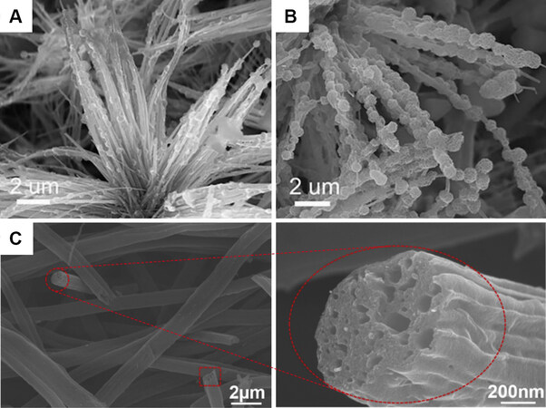
Figure 11. SEM images of (A) half and (B) fully discharged Co9S8 nanorods[36]. Reproduced from Ref.[36] with permission from John Wiley and Sons. (C) SEM images of the cathode obtained by electrospinning at magnifications of 2 μm and 200 nm[64]. Reproduced from Ref.[64] with permission from Elsevier. SEM: Scanning electron microscopy.
As a strategy to adjust the cathode structure of SOBs, Tovini et al.[59] prepared a 3D RuO2/Mn2O3/carbon nanofiber (RMC) structure with a bifunctional electrocatalyst through a simple microwave process. RuO2 nanoparticles were attached to Mn2O3 nanorods grown on carbon nanofibers (CNFs). Both the nanoscale catalysts were grown on CNF skeletons by microwave manipulation for a short time. The SOB equipped with the RMC structure exhibited a capacity of 9352 mAh g-1, seven times that of the CNF-only battery. Due to the synergistic effect of the two catalysts on the cathode-electrolyte interface, the battery exhibited excellent ORR/OER activity.
The modification of graphene oxide (GO) materials by Sun et al.[37] resulted in products that could be used to make cathode for LOBs. GO was synthesized using a modified Hummers method[60,61]. Porous graphene with different aperture structures could be obtained by using silica beads with different diameters (prepared by the Stöber method[62,63]) and treatment with concentrated hydrochloric acid. The results were also confirmed by SEM and TEM images. In the process of testing batteries made of different materials, a significant difference in capacity was observed. The treated porous graphene displayed a higher capacity than the non-porous graphene without any treatment, regardless of how large the pore size was. This change happened to achieve the purpose of the modification of the cathode-electrolyte interface. Because of the treatment, the reaction interface of porous graphene was much larger than that of non-porous graphene, leading to more reaction products. In subsequent refinements, the researchers loaded Ru onto the surface of the porous graphene. The OER process of the battery was improved, with a significant drop in the charging potential.
Ge et al.[57] proposed a 3D honeycomb graphene composite loaded with a Mo/Mo2C heterojunction and used it directly as a LOB cathode. The layered porous structure facilitated the penetration of liquid electrolyte, thereby enlarging the cathode-electrolyte interface and providing the necessary conditions for the rapid movement of electrons and the diffusion of Li+ and oxygen. A cycle test was performed at the current density of 100 mA g-1 and under a voltage range of 2.0 to 4.4 V. The battery based on the 3D Mo/Mo2C cathode exhibited a discharge capacity of ~12016 mAh g-1 and a charge capacity of
Electrospinning technology has played a significant role in the field of energy materials in recent years due to its simple and effective advantages in producing nanofibers. Electrospun nanofibers have a high specific surface area and porosity, in line with the characteristics of cathode materials used for lithium-oxygen batteries. Dong et al.[64] added MWCNTs in the electrospinning process to increase the porosity of the cathode. A homogeneous distribution of carbon fibers was clearly observed in the product [Figure 11C], with a diameter of ~2 μm. Under a magnification of 200 nm, the cross section of the hollow carbon fibers filled with holes can also be seen, just like a lotus root that has been cut. In the subsequent electrochemical test process, a larger discharge capacity (approximately seven times that of batteries with an ordinary carbon nanotube material) was obtained. The development of electrospinning technology has provided more possibilities for the preparation of cathode materials for lithium-oxygen batteries. The products obtained by this technology showed excellent potential to develop favorable structured materials for LOB cathodes.
3D printing technology has been critical for streamlined materials production in recent years. The porous cathodes of metal-O2 batteries can also be prepared simply through structural design, materials preparation and other steps. Lin et al.[65] designed a new air cathode for SOBs to enhance the poor circulation performance caused by underuse of the cathode. The cathode was stacked with multiple reduced graphene oxide (rGO) slices with a macroscopic open structure that forms open channels to ensure the continuous transmission of O2 and the full penetration of the electrolyte and the storage space of NaO2. In addition, rGO increased the electron transport rate. The extension of battery life suggested that 3D printing technology may become an efficient tool for creating next-generation cathodes.
In addition to improving the structure and morphology of cathodes, optimizing the chemical composition of cathode materials can also enhance the performance of metal-O2 batteries. Traditional porous cathodes are usually composed of a carbon material, polymer binder and catalyst. The polymer binder ensures electrical connectivity and mechanical stability. However, in the process of contact between the cathode material and electrolyte, the polymer binder (such as PVDF) can decompose the electrolyte, leading to a side reaction, as well as the binder itself being easily degraded[66-70]. Therefore, researchers have sought to achieve binder-free cathodes by adjusting their structures and chemical compositions.
The preparation and performance of nitrogen-doped carbon materials have important research value and application potential. Nitrogen doping can greatly improve the electrochemical and catalytic performance of carbon materials. Ma et al.[73] prepared a nitrogen-doped cathode structure with high porosity through a typical synthesis method. In the SEM images, the pure carbon material showed a massive structure, while the nitrogen-doped carbon showed a plicate sheet structure with pores. The contact interface between the electrolyte and cathode was enlarged, which was beneficial to the deposition of the discharge products. Melamine was added as the nitrogen source before heat treatment at 850 °C and SOBs with this material exhibited the highest capacity. The battery life was also several times higher than that with pure carbon.
Cathode modification is generally focused in two directions, namely, cathode structure and cathode material. It should be noted that both modification methods must ensure that the porous cathode structure cannot be damaged so that the cathode has more reaction sites and carries more discharge products. The battery after the structural modification exhibits a higher specific capacity than the ordinary one and novel materials also provide more possibilities for improving battery life.
Electrolyte modification
There are issues associated with side reactions caused by electrolyte decomposition and volatilization in conventional AMOBs. Some researchers have proposed that cathode-electrolyte interface could also be tuned by redesigning the electrolyte[38,40,74,75] so that alkali metal ions can achieve higher transmission speeds. The increase in the interface provides a stable space for the reaction of the cathode, which can be proved from the improvement in the battery capacity and other related properties.
In addition to its use in producing fibrous cathodes, electrospinning technology has also been used for the performance improvement of electrolytes, especially GPEs. A GPE can be tightly attached on the surface of a cathode by electrospinning in situ on the electrode surface directly. Wang et al.[74] introduced this technology into the lithium-ion battery assembly process. In their structure [Figure 12A], the new electrolyte featured a dense network and there was a close bond with the electrode. Compared with the performance of the traditional layered structure battery, the specific capacity, rate performance and cycling stability of the new battery were significantly improved. This was due to the tight bonding between the electrode and the electrolyte, and the significantly reduced ion transfer resistance. This method was used to improve the performance of lithium-ion batteries with an electrode made of LiFePO4, but related reports indicated that GPE materials could be adhered to the surface of carbon materials. Therefore, it should be possible that a cathode-electrolyte integrated structure for LOBs could also be prepared by the electrospinning method.
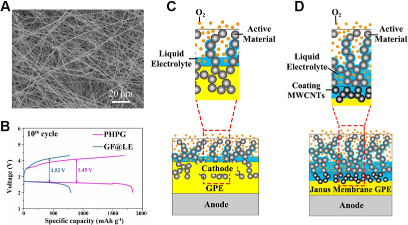
Figure 12. (A) Top-view SEM images of PVDF-HFP nanofiber matrices prepared on LiFePO4 electrode[74]. Reproduced from Ref.[74] with permission from John Wiley and Sons. (B) Charge/discharge performance of PHPG- and GF@LE-based LOBs at the 10th cycle at
Yang et al.[75] developed a polymer electrolyte with a three-dimensional porous structure known as a PHPG. Although their main purpose was to inhibit the growth of lithium dendrites during the use of lithium-oxygen batteries, it also regulated the interface between the cathode and electrolyte to a certain extent, as demonstrated by a significant increase in the battery capacity. In the preparation of the GPE, PEO and PVDF-HFP were introduced. Due to the interaction between the two polymers, the crystallinity was reduced and the transportation rate of lithium ions was promoted. The GO was also cross-linked with the two polymers by weak bonds. Subsequent electrochemical test results [Figure 12B] showed the superiority of the newly-designed electrolyte to the glass fiber-supported liquid electrolyte. The capacity was improved and the charge and discharge overpotentials were significantly lower than those of batteries using liquid electrolytes.
Based on poly(vinyl formal) (PVFM), Meng et al.[38] designed a GPE layer known as a Janus membrane, which significantly enhances the lifetime and specific capacity of LOBs. In their previous studies, PVFM was developed as a suitable substrate for gel electrolytes in lithium batteries due to its high ionic conductivity and good chemical stability. They first prepared a cross-linked PVFM membrane by phase inversion and then coated the porous surfaces of PVFM with a slurry consisting of MWCNTs, deionized water and N-methyl pyrrolidone to obtain the Janus membrane. Through SEM, a handful of CNTs were observed to infiltrate into the PVFM film, which was reported to enhance the mechanical properties of the GPE. After assembling the cells, they found that the surface coated with CNTs retained more of the solvent, which helped form a thin wet layer of electrolyte at the cathode, creating a stable diffusion channel for lithium ions. The conventional cell structure using the GPE [Figure 12C] and the novel cell structure using the Janus membrane [Figure 12D] were compared. The porous coating provided sufficient space for the discharge products because large particles of Li2O2 could be detected on the surface of the Janus membrane. At a current density of
Ha et al.[40] created a double layer of an ionogel and an ionic liquid electrolyte for Na-O2 cells instead of the single electrolyte layer used in traditional structures. The ionogel was in direct contact with the metal negative electrode, while the liquid electrolyte laid between the gel and cathode. According to the SEM images of the cathode and separator with the electrolyte after discharge, the discharge products NaO2 and Na2O2 were deposited on the surface of the cathode and separator. The ionogel prevented the bidirectional cross diffusion of O2 and degradation of the material from sodium metal. This not only delayed the corrosion of sodium metal but also restrained the film-like by-products on the cathode-electrolyte interface. The electrochemical tests exhibited a superior Coulomb efficiency of nearly 100%.
In this section, in addition to using new materials, new techniques, such as electrospinning, were also used for electrolyte modification. In future work, research activities could focus on how to keep the electrolyte in the cathode for longer.
CONCLUSION AND OUTLOOK
In the process of summarizing the latest techniques for fabricating novel cathode-electrolyte interfaces in AMOBs, an interesting finding can be readily found, namely, that the modification of LOBs accounts for the majority of studies, not only because the theoretical energy density of LOBs is higher than the other two batteries, but also its technical achievements are the most mature. It is found that the essential purpose of these strategies is to enlarge the cathode-electrolyte interface since it determines the special reaction mechanism of AMOBs. To improve the performance of AMOBs, researchers have sought to create a continuous ion-electron-oxygen transport channel. In their research results, the improvement of the battery capacity was obvious. This is because with the expansion of the cathode-electrolyte interface, the reaction sites in the battery increased dramatically, which significantly enhanced the carrying capacity of discharge product. Compared with the conventional sandwich-structured cell, the active site of the reaction extended from a plane to the whole cathode. In addition, several methods were confirmed to effectively reduce the impedance of the battery and accelerated the motion rate of ions and electrons, resulting in an enhancement in the cycling performance of the battery and a prolongation of its life.
Liquid electrolytes have been widely used in AMOBs due to their high ionic conductivity and good contact with the electrodes. However, considering the safety issues caused by electrolyte leakage and anode dendrites[76-78], GPEs have been introduced as alternative electrolytes because they combines the advantages of solid and liquid electrolytes. We have reason to believe that AMOBs based on polymer electrolytes will occupy an increasingly important position in the future. In the modification method of the mixed electrolyte and cathode material, most researchers have focused on addressing the shortcomings of insufficient contact between the polymer electrolyte and the cathode material. From simple mixing to the method of high-pressure forming, and then to electrolyte filling technology, all these methods are to change the LOBs from the traditional sandwich structure to an integrated structure. In the latter structure, the polymer electrolyte and the cathode material are responsible for the conduction of ions and electrons, respectively. In addition, this integrated structure is also loose and porous, because oxygen needs to participate in the reaction.
Among all the preparation methods of polymer-based electrolytes, the method containing photoinitiators seems to be relatively simple and effective and provides an excellent reference to researchers focusing on Li-CO2 batteries[79]. The electrolyte precursor with a photoinitiator added only needs to be irradiated with
Some noble and transition metal nanoparticles have also shown their capability in improving the OER performance[80]. For example, there have been published methods of loading Ru on modified graphene oxide or carbon black[81-83]. Batteries using these materials could be charged below 4 V. Some researchers have also devoted their attention to gel electrolytes. Some additives have been added to the electrolyte precursor as soluble catalysts in the OER process. For example, Guo et al.[84] added 50 mM LiI to the polymer electrolyte, with the modified battery exhibiting a longer lifetime than the LiI-free one. Some other substances containing halogen elements (such as Br) have also been proven to improve cell performance[85]. In addition, a work published in 2013 showed that the redox mediator tetrathiafulvalene can also effectively reduce the overcharge potential[86,87]. A variety of additives provide us with more ideas for improving the cathode-polymer electrolyte integrated structure.
Integrated electrolytes and cathodes can eliminate the interfacial resistance. One of the key techniques of this method is to find a suitable solid electrolyte material as a framework to support and store the discharge products. In addition, it is necessary to use a suitable method to make the material porous. At present, the most commonly used approach is to mix the electrolyte powder and starch at a high temperature to form the electrolyte layer used for the battery[56]. However, solid electrolytes have inherent defects, such as low ionic conductivity and poor interfacial performance with lithium metal, which lead to a further increase in impedance. Therefore, the popularization of solid electrolytes still requires continued research efforts.
A variety of materials and novel methods, including electrospinning and 3D printing, have been used in the reformation of cathodes and electrolytes. The improvement of the cathode focuses on the use of appropriate methods to increase the specific surface area and changing the chemical composition, such as constructing a new structure or making it porous with chemical reagents. In addition, achieving a binder-free cathode can also enhance the performance of the battery. However, in the assembly process of the cell, the constraints of the liquid electrolyte cannot be ignored, which means that the battery may suffer from safety problems like other liquid electrolyte batteries.
Different from LOBs and SOBs, K-O2 batteries have different discharge mechanisms. The cathode reaction of Li-O2 batteries has two different discharge competitive routes: the solution route and the surface route[88]. The product of surface discharge, a Li2O2 film, leads to lower capacity and rate performance compared with the solution discharge mechanism[89-91]. A study published in 2018 indicated that K-O2 cells have a high-capacity surface route[92]. Although the cause of this effect is still unclear, it remains of great significance for the cathode structural design and cathode-electrolyte modification of K-O2 cells. For the modification of the electrolyte, researchers have mainly focused on the enhancement of the stability of the interface between the anode and the electrolyte. However, even after the modification, it is found that the performance improvement is also reflected in the other interface, so the importance of improving the cathode-electrolyte interface should also be taken seriously. After overcoming the above issues, alkali-metal-O2 batteries would surely be improved significantly and their future applications will hold great promise.
DECLARATIONS
Authors’ contributionsConceived the manuscript: Liu L, Wu Y
Wrote the manuscript: Peng X
Reviewed the manuscript: Liu L, Wu Y
Contributed to the discussion of the manuscript: Peng X, Wang C, Liu Y, Fang W, Zhu Y, Fu L, Ye J, Liu L, Wu Y
Availability of data and materialsNot applicable.
Financial support and sponsorshipThis work was supported by the National Natural Science Foundation of China (No. 52002171), the Natural Science Foundation of Jiangsu Province (No. BK20200696, No. BK20200768, No. 20KJB430019).
Conflicts of interestAll authors declared that there are no conflicts of interest.
Ethical approval and consent to participateNot applicable.
Consent for publicationNot applicable.
Copyright© The Author(s) 2021.
REFERENCES
1. Tan P, Jiang H, Zhu X, et al. Advances and challenges in lithium-air batteries. Appl Energy 2017;204:780-806.
2. Kwak WJ, Rosy, Sharon D, et al. Lithium-oxygen batteries and related systems: potential, status, and future. Chem Rev 2020;120:6626-83.
3. Gao X, Chen Y, Johnson LR, Jovanov ZP, Bruce PG. A rechargeable lithium-oxygen battery with dual mediators stabilizing the carbon cathode. Nat Energy 2017;2:1-7.
4. Bi X, Wang R, Amine K, Lu J. A critical review on superoxide-based sodium-oxygen batteries. Small Methods 2019;3:1800247.
5. Das SK, Lau S, Archer LA. Sodium-oxygen batteries: a new class of metal-air batteries. J Mater Chem A 2014;2:12623.
6. Ren X, Lau KC, Yu M, et al. Understanding side reactions in K-O2 batteries for improved cycle life. ACS Appl Mater Interfaces 2014;6:19299-307.
7. Qin L, Schkeryantz L, Zheng J, Xiao N, Wu Y. Superoxide-based K-O2 batteries: highly reversible oxygen redox solves challenges in air electrodes. J Am Chem Soc 2020;142:11629-40.
8. Hong Y, Zhao C, Xiao Y, et al. Safe lithium-metal anodes for Li-O2 batteries: from fundamental chemistry to advanced characterization and effective protection. Batteries & Supercaps 2019;2:638-58.
9. Jung HG, Hassoun J, Park JB, Sun YK, Scrosati B. An improved high-performance lithium-air battery. Nat Chem 2012;4:579-85.
10. Mccloskey BD, Scheffler R, Speidel A, Girishkumar G, Luntz AC. On the mechanism of nonaqueous Li-O2 electrochemistry on C and its kinetic overpotentials: some implications for Li-air batteries. J Phys Chem C 2012;116:23897-905.
11. Black R, Lee JH, Adams B, Mims CA, Nazar LF. The role of catalysts and peroxide oxidation in lithium-oxygen batteries. Angew Chem Int Ed Engl 2013;52:392-6.
12. Zhang D, Wang B, Jiang Y, et al. Enhanced electrocatalytic performance of Co3O4/Ketjen-black cathodes for Li-O2 batteries. J Alloys Compd 2015;653:604-10.
13. Xu P, Zhu J, Chen C, Xie J, Wang M. Bi2S3/Ketjen black as a highly efficient bifunctional catalyst for long-cycle lithium-oxygen batteries. ChemElectroChem 2019;6:3885-91.
14. Yu R, Fan W, Guo X, Dong S. Highly ordered and ultra-long carbon nanotube arrays as air cathodes for high-energy-efficiency Li-oxygen batteries. J Power Sources 2016;306:402-7.
15. Xia G, Shen S, Zhu F, et al. Effect of oxygen-containing functional groups of carbon materials on the performance of Li-O2 batteries. Electrochem Communs 2015;60:26-9.
16. Xu SM, Liang X, Ren ZC, Wang KX, Chen JS. Free-standing air cathodes based on 3D hierarchically porous carbon membranes: kinetic overpotential of continuous macropores in Li-O2 batteries. Angew Chem Int Ed Engl 2018;57:6825-9.
17. Liu L, Ma T, Fang W, et al. Facile fabrication of Ag nanocrystals encapsulated in nitrogen-doped fibrous carbon as an efficient catalyst for lithium oxygen batteries. Energy Environ Mater 2021;4:239-45.
18. Liu L, Guo H, Hou Y, et al. A 3D hierarchical porous Co3O4 nanotube network as an efficient cathode for rechargeable lithium-oxygen batteries. J Mater Chem A 2017;5:14673-81.
19. Hou Y, Wang J, Liu J, et al. Interfacial super - assembled porous CeO2/C frameworks featuring efficient and sensitive decomposing Li2O2 for smart Li-O2 batteries. Adv Energy Mater 2019;9:1901751.
20. Hou Y, Wang J, Hou C, et al. Oxygen vacancies promoting the electrocatalytic performance of CeO2 nanorods as cathode materials for Li-O2 batteries. J Mater Chem A 2019;7:6552-61.
21. Zhang J, Sun B, Xie X, Kretschmer K, Wang G. Enhancement of stability for lithium oxygen batteries by employing electrolytes gelled by poly(vinylidene fluoride-co-hexafluoropropylene) and tetraethylene glycol dimethyl ether. Electrochimica Acta 2015;183:56-62.
22. Tong B, Huang J, Zhou Z, Peng Z. The salt matters: enhanced reversibility of Li-O2 batteries with a Li[(CF3SO2)(n-C4F9SO2)N]-based electrolyte. Adv Mater 2018;30:1704841.
23. Liu QC, Xu JJ, Yuan S, et al. Artificial protection film on lithium metal anode toward long-cycle-life lithium-oxygen batteries. Adv Mater 2015;27:5241-7.
24. Kozen AC, Lin C, Zhao O, Lee SB, Rubloff GW, Noked M. Stabilization of lithium metal anodes by hybrid artificial solid electrolyte interphase. Chem Mater 2017;29:6298-307.
25. Hirshberg D, Sharon D, De La Llave E, et al. Feasibility of full (Li-Ion)-O2 cells comprised of hard carbon anodes. ACS Appl Mater Interfaces 2017;9:4352-61.
26. Zhang Y, Wang L, Guo Z, Xu Y, Wang Y, Peng H. High-performance lithium-air battery with a coaxial-fiber architecture. Angew Chem Int Ed Engl 2016;55:4487-91.
27. Zhang T, Liao K, He P, Zhou H. A self-defense redox mediator for efficient lithium-O2 batteries. Energy Environ Sci 2016;9:1024-30.
28. Walker W, Giordani V, Uddin J, Bryantsev VS, Chase GV, Addison D. A rechargeable Li-O2 battery using a lithium nitrate/N,N-dimethylacetamide electrolyte. J Am Chem Soc 2013;135:2076-9.
29. Bryantsev VS, Giordani V, Walker W, et al. Investigation of fluorinated amides for solid-electrolyte interphase stabilization in Li-O2 batteries using amide-based electrolytes. J Phys Chem C 2013;117:11977-88.
30. Lyu Z, Zhou Y, Dai W, et al. Recent advances in understanding of the mechanism and control of Li2O2 formation in aprotic Li-O2 batteries. Chem Soc Rev 2017;46:6046-72.
31. Mushtaq M, Guo X, Wang Y, Hao L, Lin Z, Yu H. Composite cathode architecture with improved oxidation kinetics in polymer-based Li-O2 batteries. ACS Appl Mater Interfaces 2020;12:30259-67.
32. Zhang T, Zhou H. From Li-O2 to Li-air batteries: carbon nanotubes/ionic liquid gels with a tricontinuous passage of electrons, ions, and oxygen. Angew Chem Int Ed Engl 2012;51:11062-7.
33. Zhu XB, Zhao TS, Wei ZH, Tan P, Zhao G. A novel solid-state Li-O2 battery with an integrated electrolyte and cathode structure. Energy Environ Sci 2015;8:2782-90.
34. Xiao L, Li E, Yi J, Meng W, Deng B, Liu J. Enhanced performance of solid-state Li-O2 battery using a novel integrated architecture of gel polymer electrolyte and nanoarray cathode. Rare Met 2018;37:527-35.
35. Zhu XB, Zhao TS, Wei ZH, Tan P, An L. A high-rate and long cycle life solid-state lithium-air battery. Energy Environ Sci 2015;8:3745-54.
36. Lin X, Yuan R, Cai S, et al. An open-structured matrix as oxygen cathode with high catalytic activity and large Li2O2 accommodations for lithium-oxygen batteries. Adv Energy Mater 2018;8:1800089.
37. Sun B, Huang X, Chen S, Munroe P, Wang G. Porous graphene nanoarchitectures: an efficient catalyst for low charge-overpotential, long life, and high capacity lithium-oxygen batteries. Nano Lett 2014;14:3145-52.
38. Meng N, Lian F, Li Y, et al. Exploring PVFM-based janus membrane-supporting gel polymer electrolyte for highly durable Li-O2 batteries. ACS Appl Mater Interfaces 2018;10:22237-47.
39. Huang Z, Deng Z, Shen Y, et al. A Li-O2 battery cathode with vertical mass/charge transfer pathways. J Mater Chem A 2019;7:3000-5.
40. Ha TA, Fdz De Anastro A, Ortiz-Vitoriano N, et al. High coulombic efficiency Na-O2 batteries enabled by a bilayer ionogel/ionic liquid. J Phys Chem Lett 2019;10:7050-5.
41. Kim CHJ, Varanasi CV, Liu J. Synergy of polypyrrole and carbon x-aerogel in lithium-oxygen batteries. Nanoscale 2018;10:3753-8.
42. Zhou B, Guo L, Zhang Y, et al. A high-performance Li-O2 battery with a strongly solvating hexamethylphosphoramide electrolyte and a LiPON-protected lithium anode. Adv Mater 2017;29:1701568.
43. Manuel Stephan A. Review on gel polymer electrolytes for lithium batteries. Eur Polym J 2006;42:21-42.
44. Cho YG, Hwang C, Cheong DS, Kim YS, Song HK. Gel/Solid polymer electrolytes characterized by in situ gelation or polymerization for electrochemical energy systems. Adv Mater 2019;31:e1804909.
45. Li X, Shao J, Kim SK, et al. High energy flexible supercapacitors formed via bottom-up infilling of gel electrolytes into thick porous electrodes. Nat Commun 2018;9:2578.
46. Wang J, Ni Y, Liu J, et al. Room-temperature flexible quasi-solid-state rechargeable Na-O2 batteries. ACS Cent Sci 2020;6:1955-63.
47. Song E, Shin J, Lee S, Kim S. Infilling of highly ion-conducting gel polymer electrolytes into electrodes with high mass loading for high-performance energy storage. J Ind Eng Chem 2020;87:173-9.
48. Matsuda S, Yamaguchi S, Yasukawa E, et al. Effect of electrolyte filling technology on the performance of porous carbon electrode-based lithium-oxygen batteries. ACS Appl Energy Mater 2021;4:2563-9.
49. Chen C, Xu S, Kuang Y, et al. Nature-inspired tri-pathway design enabling high-performance flexible Li-O2 batteries. Adv Energy Mater 2019;9:1802964.
50. Jiang Z, Xu G, Yu Z, et al. High rate and long cycle life in Li-O2 batteries with highly efficient catalytic cathode configured with
51. Zeng J, Francia C, Amici J, Bodoardo S, Penazzi N. Mesoporous Co3O4 nanocrystals as an effective electro-catalyst for highly reversible Li-O2 batteries. J Power Sources 2014;272:1003-9.
52. Chi X, Li M, Di J, et al. A highly stable and flexible zeolite electrolyte solid-state Li-air battery. Nature 2021;592:551-7.
53. Bonnet-Mercier N, Wong RA, Thomas ML, et al. A structured three-dimensional polymer electrolyte with enlarged active reaction zone for Li-O2 batteries. Sci Rep 2014;4:7127.
54. Kitaura H, Zhou H. Electrochemical performance of solid-state lithium-air batteries using carbon nanotube catalyst in the air electrode. Adv Energy Mater 2012;2:889-94.
55. Gao K, Wang H, He M, et al. Interfacial integration and roll forming of quasi-solid-state Li-O2 battery through solidification and gelation of ionic liquid. J Power Sources 2020;463:228179.
56. Li C, Liu Y, Li B, et al. Integrated solid electrolyte with porous cathode by facilely one-step sintering for an all-solid-state Li-O2 battery. Nanotechnology 2019;30:364003.
57. Ge B, Wang J, Sun Y, Guo J, Fernandez C, Peng Q. Heterojunction-composited architecture for Li-O2 batteries with low overpotential and long-term cyclability. ACS Appl Energy Mater 2020;3:3789-97.
58. Gilmore P, Sundaresan VB. A functionally graded cathode architecture for extending the cycle-life of potassium-oxygen batteries. Batteries & Supercaps 2019;2:678-87.
59. Tovini MF, Patil B, Koz C, Uyar T, Yılmaz E. Nanohybrid structured RuO2/Mn2O3/CNF as a catalyst for Na-O2 batteries. Nanotechnology 2018;29:475401.
60. Frankberg EJ, George L, Efimov A, Honkanen M, Pessi J, Levänen E. Measuring synthesis yield in graphene oxide synthesis by modified hummers method. Fuller Nanotub Carbon Nanostructures 2014;23:755-9.
61. Vazquez-jaime M, Arcibar-orozco J, Damian-ascencio C, et al. Effective removal of arsenic from an aqueous solution by ferrihydrite/goethite graphene oxide composites using the modified Hummers method. J Environ Chem Eng 2020;8:104416.
62. Wong YJ, Zhu L, Teo WS, et al. Revisiting the Stöber method: inhomogeneity in silica shells. J Am Chem Soc 2011;133:11422-5.
63. Ghimire PP, Jaroniec M. Renaissance of Stöber method for synthesis of colloidal particles: new developments and opportunities. J Colloid Interface Sci 2021;584:838-65.
64. Dong H, Li K, Wang Y, Yin Y, Yang S. Preparation of pyridine N-doped metal-free Li-O2 battery cathode by one-step. Electrochimica Acta 2020;330:135231.
65. Lin X, Wang J, Gao X, et al. 3D printing of free-standing “O2 breathable” air electrodes for high-capacity and long-life Na-O2 batteries. Chem Mater 2020;32:3018-27.
66. Nasybulin E, Xu W, Engelhard MH, Nie Z, Li XS, Zhang J. Stability of polymer binders in Li-O2 batteries. J Power Sources 2013;243:899-907.
67. Amanchukwu CV, Harding JR, Shao-horn Y, Hammond PT. Understanding the chemical stability of polymers for lithium-air batteries. Chem Mater 2015;27:550-61.
68. Sun Q, Lin X, Yadegari H, et al. Aligning the binder effect on sodium-air batteries. J Mater Chem A 2018;6:1473-84.
69. Yadegari H, Sun Q, Sun X. Sodium-oxygen batteries: a comparative review from chemical and electrochemical fundamentals to future perspective. Adv Mater 2016;28:7065-93.
70. Papp JK, Forster JD, Burke CM, et al. Poly(vinylidene fluoride) (PVDF) binder degradation in Li-O2 batteries: a consideration for the characterization of lithium superoxide. J Phys Chem Lett 2017;8:1169-74.
71. Pozo-Gonzalo C, Zhang Y, Ortiz-Vitoriano N, et al. Controlling the three-phase boundary in Na-oxygen batteries: the synergy of carbon nanofibers and ionic liquid. ChemSusChem 2019;12:4054-63.
72. Jian Z, Chen Y, Li F, Zhang T, Liu C, Zhou H. High capacity Na-O2 batteries with carbon nanotube paper as binder-free air cathode. J Power Sources 2014;251:466-9.
73. Ma J, Zhang X. Optimized nitrogen-doped carbon with a hierarchically porous structure as a highly efficient cathode for Na-O2 batteries. J Mater Chem A 2016;4:10008-13.
74. Wang L, Zhang R, Dai H, et al. Reinforce the adhesion of Gel electrolyte to electrode and the interfacial charge transfer via in situ electrospinning the polymeric nanofiber matrix. Energy Technol 2021;9:2000865.
75. Yang T, Shu C, Hou Z, et al. 3D porous network gel polymer electrolyte with high transference number for dendrite-free Li O2 batteries. Solid State Ionics 2019;343:115088.
76. Zhao C, Sun Q, Luo J, et al. 3D porous garnet/Gel polymer hybrid electrolyte for safe solid-state Li-O2 batteries with long lifetimes. Chem Mater 2020;32:10113-9.
77. Liao K, Wu S, Mu X, et al. Developing a "water-defendable" and "dendrite-free" lithium-metal anode using a simple and promising GeCl4 pretreatment method. Adv Mater 2018;30:e1705711.
78. Yi J, Guo S, He P, Zhou H. Status and prospects of polymer electrolytes for solid-state Li-O2 (air) batteries. Energy Environ Sci 2017;10:860-84.
79. Li C, Guo Z, Yang B, Liu Y, Wang Y, Xia Y. A rechargeable Li-CO2 battery with a Gel polymer electrolyte. Angew Chem Int Ed Engl 2017;56:9126-30.
80. Lim H, Song H, Gwon H, et al. A new catalyst-embedded hierarchical air electrode for high-performance Li-O2 batteries. Energy Environ Sci 2013;6:3570.
81. Sun B, Munroe P, Wang G. Ruthenium nanocrystals as cathode catalysts for lithium-oxygen batteries with a superior performance. Sci Rep 2013;3:2247.
82. Zhong G, Xu S, Cui M, et al. Rapid, high-temperature, in situ microwave synthesis of bulk nanocatalysts. Small 2019;15:e1904881.
83. He F, Xia N, Zheng Y, et al. In situ electrochemical fabrication of ultrasmall ru-based nanoparticles for robust N2H4 oxidation. ACS Appl Mater Interfaces 2021;13:8488-96.
84. Guo Z, Li C, Liu J, Wang Y, Xia Y. A long-life lithium-air battery in ambient air with a polymer electrolyte containing a redox mediator. Angew Chem Int Ed Engl 2017;56:7505-9.
85. Liu H, Liu M, Yang L, et al. A bi-functional redox mediator promoting the ORR and OER in non-aqueous Li-O2 batteries. Chem Commun (Camb) 2019;55:6567-70.
86. Chen Y, Freunberger SA, Peng Z, Fontaine O, Bruce PG. Charging a Li-O2 battery using a redox mediator. Nat Chem 2013;5:489-94.
87. Zhang J, Sun B, Zhao Y, Kretschmer K, Wang G. Modified tetrathiafulvalene as an organic conductor for improving performances of Li-O2 batteries. Angew Chem Int Ed Engl 2017;56:8505-9.
88. Aurbach D, Mccloskey BD, Nazar LF, Bruce PG. Advances in understanding mechanisms underpinning lithium-air batteries. Nat Energy 2016;1:1-11.
89. Johnson L, Li C, Liu Z, et al. The role of LiO2 solubility in O2 reduction in aprotic solvents and its consequences for Li-O2 batteries. Nat Chem 2014;6:1091-9.
90. Horstmann B, Gallant B, Mitchell R, Bessler WG, Shao-Horn Y, Bazant MZ. Rate-dependent morphology of Li2O2 growth in Li-O2 batteries. J Phys Chem Lett 2013;4:4217-22.
91. Adams BD, Radtke C, Black R, Trudeau ML, Zaghib K, Nazar LF. Current density dependence of peroxide formation in the Li-O2 battery and its effect on charge. Energy Environ Sci 2013;6:1772.
Cite This Article
Export citation file: BibTeX | RIS
OAE Style
Peng X, Wang C, Liu Y, Fang W, Zhu Y, Fu L, Ye J, Liu L, Wu Y. Critical advances in re-engineering the cathode-electrolyte interface in alkali metal-oxygen batteries. Energy Mater 2021;1:100011. http://dx.doi.org/10.20517/energymater.2021.15
AMA Style
Peng X, Wang C, Liu Y, Fang W, Zhu Y, Fu L, Ye J, Liu L, Wu Y. Critical advances in re-engineering the cathode-electrolyte interface in alkali metal-oxygen batteries. Energy Materials. 2021; 1(2): 100011. http://dx.doi.org/10.20517/energymater.2021.15
Chicago/Turabian Style
Peng, Xiaohui, Chen Wang, Yihao Liu, Weiwei Fang, Yusong Zhu, Lijun Fu, Jilei Ye, Lili Liu, Yuping Wu. 2021. "Critical advances in re-engineering the cathode-electrolyte interface in alkali metal-oxygen batteries" Energy Materials. 1, no.2: 100011. http://dx.doi.org/10.20517/energymater.2021.15
ACS Style
Peng, X.; Wang C.; Liu Y.; Fang W.; Zhu Y.; Fu L.; Ye J.; Liu L.; Wu Y. Critical advances in re-engineering the cathode-electrolyte interface in alkali metal-oxygen batteries. Energy Mater. 2021, 1, 100011. http://dx.doi.org/10.20517/energymater.2021.15
About This Article
Copyright

Data & Comments
Data


 Cite This Article 37 clicks

 Like This Article 39
likes
Like This Article 39
likes


Comments
Comments must be written in English. Spam, offensive content, impersonation, and private information will not be permitted. If any comment is reported and identified as inappropriate content by OAE staff, the comment will be removed without notice. If you have any queries or need any help, please contact us at support@oaepublish.com.