
Evaluation of the electrochemical and expansion performances of the Sn-Si/graphite composite electrode for the industrial use

Abstract
The future development of lithium-ion batteries for electric vehicles requires significantly higher energy density and this is largely dependent on the application of novel active materials with high specific capacity. Recently, Sn-Si hybrid materials have been shown to exhibit both high specific capacity and good cycle stability. In practice, Sn-Si materials are mixed with graphite to form composite anodes to further improve the stability. However, detailed investigations of Sn-Si/graphite anodes are scarce. This study examines the electrochemical and expansion performance of Sn-Si/graphite anodes and features a morphological, structural and chemical analysis. The percolation and lattice expansion models are shown to fit well for the capacity and expansion evolution law of the composite anodes, respectively, as a function of Sn-Si hybrid content. Based on a comparison with a conventional graphite anode, efficient Sn-Si/graphite composite anodes could be formed that achieve a high reversible capacity (450 mAh g-1), a promising 1st Coulombic efficiency (75%) and stable cycling (cycling coulombic efficiency > 98%), thereby making them some of the most promising Sn-based anodes for industrial applications.
Keywords
INTRODUCTION
Alloy-type materials, such as Si and Sn, are regarded as the “next-generation” anode materials that are closest to industrial use. Si is the most “popular” graphite-substituent candidate, owing to its highest theoretical specific capacity (up to 4200 mAh g-1), abundance and safety[1-3]. Compared to Si, nanosized Sn is currently attracting increasing attention because of its promising specific capacity (up to ~1000 mAh g-1), outstanding mixed-conductor performance (At room temperature, electrical conductivity and Li-ion diffusion coefficient of 9.17 × 10⁶ S m-1 and 5.90 × 10⁻⁷ cm2 s-1, respectively) and good cycling and rate performance[4-7]. Recently, a large-scale production method for producing carbon-coated nano Sn-Si hybrid materials with excellent performance (1st discharge capacity of > 1000 mAh g-1 for > 500 cycles) has been reported[8], thereby making it possible for the industrialization of Sn-Si hybrid active materials in the near future.
Despite these multiple advantages, the Coulombic efficiency (CE) of purely Sn-Si-based hybrids is still too low (< 96%) for industrial applications (> 99%)[9]. As a result, by considering the use of traditional electrode preparation processes, elaborating a composite anode composed of a carbonaceous matrix and Sn-Si hybrid is a rather practical and effective method to take advantage of both materials, i.e., Sn-Si hybrids to significantly increase the overall capacity[10] and carbonaceous materials, including graphite[11-13], hard carbon[14-16], graphene[17,18], to improve the cycling and restrict the expansion of the composite anode. Based on such an electrode design concept, since the beginning of the 21st century, various studies, including Wang et al.[11,12] and Fang et al.[13], have already established Sn- and Si-graphite binary anode systems and confirmed the important capacity rise with the addition of Sn/Si into the graphite. However, the Sn/Si materials used in these studies were neither nanoscale nor carbon-coated, leading to poor cycling performance. Recently, Ding et al.[18] elaborated a nano-voided Sn/graphene nanosheet anode, which delivered a good capacity of 534 mAh g-1 and achieved more than 200 cycles, thereby setting a new standard for Sn-Si hybrid/C composite anodes. However, graphene is not an electrochemically active material, leading to some specific capacity loss and a comparatively low 1st CE, thereby making it less practical for industrial applications.
In this work, locally produced carbon-coated Sn-Si hybrid nanoparticles and commercial graphite are selected to construct efficient active binary composites that achieve a high reversible capacity of 450 mAh g-1, a promising 1st CE of 75% and stable cycling with CE > 98%, thereby making them some of the most promising Sn-Si hybrid/C composite anodes for industrial use. In order to ensure the correct functionality of the Sn-Si hybrid/graphite composites, a detailed study of their electrochemical/expansion performance is conducted. A series of electrochemical, morphological and microstructural characterization methods, including scanning electron microscopy (SEM), X-ray diffraction (XRD) and X-ray photoelectron spectroscopy (XPS), are employed to examine the electrochemical reactions occurring within and surrounding the active composite materials. Both half and full cells are tested to provide a complete understanding of how the novel Sn-Si hybrid/graphite composite anodes work in Li-sufficient and real working conditions, respectively.
EXPERIMENTAL
Electrode preparation
With the exception of the Sn-Si hybrid materials, all materials were purchased from commercial distributors. The Sn-Si hybrid powder was elaborated in a local laboratory using a process described in the literature[8] with a mass ratio of Sn:Si = 4:1. During the synthesis process, the corresponding amounts of SnO2 and Si nanoparticles were premixed before reacting with C2H2 in a furnace at 400 °C for 2 h. After the reaction, SnO2 was reduced to Sn and an amorphous carbon layer was formed to cover the surface of the Sn nanoparticles.
A slurry composition of 93% Sn-Si hybrid/graphite mixed powder, 3% SBR (Styrene-butadiene rubber), 2.5% CMC (Carboxymethyl Cellulose) and 1.5% Super-P was used for the preparation of all anodes. The mass ratio of Sn-Si hybrid within the mixed Sn-Si hybrid/graphite powder was set to be 0% (pure graphite), 5%, 10%, 20% and 100% (pure Sn-Si hybrid). All the slurries were prepared using a high-speed dispersion machine (Thinky ARE-310) via the following steps:
(1) CMC was dispersed in deionized water at 1000 RPM for 20 min;
(2) The Sn-Si hybrid, graphite and Super-P were manually premixed in a mortar and then dispersed in the above prepared CMC suspension at 2000 RPM for 20 min;
(3) SBR was added and dispersed at 800 RPM for 12 min.
The slurry was coated on an 8 μm Cu foil using a commercial slot-dye coating machine (YINGSHAN, GTB250D/E-15/0502A) with a controlled coating weight of ~100 g m-2 (the areal capacity of the electrodes with 0%, 5%, 10%, 20% and 100% Sn-Si were 3.69, 3.96, 4.20, 4.41 and 10.20 mAh cm-2, respectively). After drying, the anodes were then calendared through a commercial calendar (KENUOER, NR-14025) in order to achieve a pressing density of ~1.8 g cm-3.
Battery preparation
Coin cells (half cells) were assembled using the as-elaborated anodes, lithium metal foil and a polyethylene separator. The electrolyte used in the study was 1 M LiPF6 in mixed EC/DMC solutions with 10% of FEC additives to improve the SEI stability of the anode[19].
Pouch cells (full cells) were made using the same cathode in order to compare the composite anodes and the conventional graphite anode. The detailed cell assembly information is shown in Table 1. The electrolyte composition used in the pouch cells was the same as in the coin cells. The cathodes used in the pouch cells were prepared based on a slurry composed of 94% NCM 622, 3% PVDF and 3% conductive agent, followed by the coating and calendaring process. The N/P ratio was set to 1.07 to assure the charge-discharge security.
Design information of pouch cell
| Cell dimensions | 87.35 mm * 64.5 mm * 4.88 mm | ||
| Types | NCM622-Graphite | NCM622-Composite | |
| Layers | 15 + 16 | ||
| Cathode | Active material | NCM622 | |
| Loading | 94% | ||
| Coating weight (g m-2) | 183 | ||
| Calendar density (g cm-3) | 3.5 | ||
| Al foil thickness (μm) | 14 | ||
| Anode | Active material | Graphite | Composite (Sn-Si/C = 1:9) |
| Loading | 95% | 93% | |
| Coating weight (g m-2) | 107 | 96 | |
| Calendar density (g cm-3) | 1.75 | 1.8 | |
| Cu foil thickness (μm) | 8 | ||
| EL injection (g) | 13.3 | ||
| Capacity (Ah) | 3.65 | ||
Electrochemical test
Cycling tests were conducted on coin cells with different composite electrodes. For each cycle, the coin cell was discharged to 0.005 V at 0.05 C and then 0.05 C constant current to 1 V followed by a constant voltage region at 1 V until 0.02 C. All galvanostatic measurements of the coin cells were performed on a multichannel battery cycler (LANHE CT3001A).
Before the cycling tests, the pouch cells had already gone through a formation process, during which they were firstly charged to 3.0 V at 0.02 C, followed by a second charge to 3.8 V at 0.05 C. In the subsequent cycles, the pouch cells repeated the charge and discharge in a voltage range of 3.0 to 4.2 V with a constant rate of 0.05 C. The charge capacity during the formation, as well as the charge and discharge capacity during the 1st cycle were used together for the calculation of the 1st CE. All galvanostatic measurements of the pouch cells were performed on a multichannel battery cycler (Newware CT-4008-5V100A).
Characterization methods
The morphological characterization of the raw materials and the electrodes before lithiation was performed by scanning electron microscopy (SEM, Hitachi S-4800) coupled to an energy dispersive spectrometer. The SEM photographs of the electrodes after lithiation were taken using a ZEISS instrument.
XRD (Bruker D8 Advance) with Cu Kα radiation (λ = 1.54 Å) and XPS (Thermo Fisher ESCA Xi+) were employed to characterize the microstructure and the SEI products of the active materials, respectively. The lithiated electrode samples were washed in DMC to remove the electrolyte components. All the samples were dried and sealed in containers under dry conditions (dew point < -40 °C) and were taken out rapidly for the XRD and XPS tests in order to avoid sample exposure to the atmosphere as much as possible. The deconvolution of peaks for the XPS spectra was conducted using the open-source software XPS Peak Fit. Each spectrum was fit to a Shirley type background. Peak positions were fixed according to the handbook[20] and were fitted as asymmetric Gaussian/Lorentzian curves with 0%-30% Lorentzian character.
The expansion rate was calculated based on the thickness of the electrodes before and after lithiation to 0.005 V. The thickness of the electrodes was measured using a micrometer (precision of 0.1 μm).
Percolation model assumption for a binary composite
The specific capacity of a composite anode is the sum of the specific capacity of each active constituent multiplied by its mass percentage, as shown in Equation (1):
Ccomposite = Cgraphite × ηgraphite+ Csn-si × ηsn-si (1)
where Ccomposite, Cgraphite and Csn-si represent the specific capacity of the composite anode, the pure graphite and the pure Sn-Si hybrid, respectively, and ηgraphite and ηsn-si represent the mass ratios of graphite and Sn-Si within the Sn-Si/graphite mixture, respectively.
Lattice expansion model assumption
The total volume expansion of an electrode is the sum of the lattice expansion of each component multiplied by its corresponding volumetric ratio:
ΔTelectrode% = ΔTgraphite% × Vgraphite% + ΔTsn-si% × Vsn-si% (2)
where Vgraphite% and Vsn-si% were calculated based on their mass ratios and the corresponding true densities (skeletal densities[21]), as displayed in Table 2. The true densities used for the volumetric ratio calculations were measured by a gas displacement pycnometer system (BSD-TD, China) and were 2.253 g cm-3 (graphite), 4.110 g cm-3 (Sn-Si hybrid), 1.131 g cm-3 (binders) and 2.0177 g cm-3 (Super-P). The theoretical lattice expansion rates for graphite and the Sn-Si hybrid were 14%[22] and 286%[6,23], respectively.
Volumetric ratios used in the lattice expansion model
| Electrode component | Sn-Si mass ratio | |||||
| 0% | 10% | 20% | ||||
| Wt.% | V% | Wt.% | V% | Wt.% | V% | |
| Graphite | 93% | 88.0% | 83.7% | 82.5% | 74.4% | 76.5% |
| Sn-Si | 0% | 0% | 9.3% | 5.0% | 18.6% | 10.5% |
| Others | 7% | 12.0% | 7% | 12.5% | 7% | 13.0% |
RESULTS AND DISCUSSION
Morphology of active materials
The micrographs of the locally produced Sn-Si hybrid nanoparticles, the commercially purchased graphite and the resulting composite anode are shown in Figure 1. The single Sn-Si hybrid powder is sized from 1 to 5 μm [Figure 1A] and is in form of a secondary aggregate composed of large amounts of primary Sn-Si hybrid nanoparticles. According to Figure 1B, the primary Sn-Si hybrid nanoparticles have an average diameter of ~100 nm and are covered by an amorphous carbon layer. The nanosizing and carbon coating design are essential for ensuring good cycle stability for alloy-type materials[24-26]. The graphite purchased has a rather important length to diameter ratio [Figure 1C] for the intention of improving the calendaring density, especially when used in combination with spherical Sn-Si hybrid particles. The importance of the calendaring density to the energy density of the battery has been largely discussed[27-29].
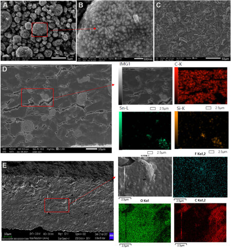
Figure 1. Scanning electron microscopy pictures of (A) used Sn-Si hybrid nanoparticles, (B) graphite and the (C) resulting Sn-Si hybrid/graphite composite anode (Sn-Si hybrid/C mass ratio = 1:9) (D) before and (E) after the 1st lithiation.
In the resulting composite anode, as displayed in Figure 1D, the Sn-Si hybrid and graphite particles can be clearly identified from either SEM or EDX. With these techniques, the Sn-Si hybrid secondary particles appear as grey spheres uniformly immersed in a dark graphite matrix, implying the correct distribution of both active materials. However, after lithiation, none of the graphite or Sn-Si hybrid could be clearly identified from SEM [Figure 1E], whereas the SEI is observed to cover the whole surface of the electrode with the main elements detected are fluorine, oxygen and carbon, which are normally the SEI components.
Electrochemical and expansion performance of composite anodes
The voltage-specific capacity profiles of the single graphite and Sn-Si hybrid during the lithiation and delithiation of the 2nd cycle are shown in Figure 2A and B, respectively. Graphite exhibits three typical lithiation reaction peaks at 0.20, 0.12 and 0.07 V and three corresponding delithiation peaks with a small overpotential of 20-30 mV, which confirms its good reversibility during cycling. The Sn-Si hybrid lithiation consists of four Sn-related reactions at 0.66, 0.56, 0.43 and 0.25 V and one Si-related reaction at 0.10 V. With respect to these, five delithiation reactions with a slightly higher overpotential of 120-180 mV occur for the Sn-Si hybrid, in good agreement with the literature[5].
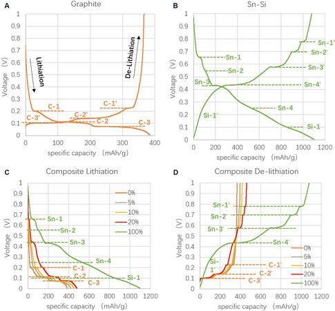
Figure 2. Lithiation and delithiation profile at 2nd cycle of (A) single graphite, (B) single Sn-Si hybrid and (C) and (D) the composite anodes with different ratios of Sn-Si.
The lithiation and delithiation profiles of the Sn-Si hybrid/C composite anodes with different Sn-Si hybrid/C ratios display a coexistence of the reactions of both the Sn-Si hybrid and graphite, as shown in Figure 2C and D. Such profiles indicate a successful release of the electrochemical activity of each component in the composite anodes regardless of the mass ratios. Moreover, all of the voltage-capacity profiles of the composite anodes are within that of the single Sn-Si hybrid and single graphite and successively tend to approach the profile of their predominant component (Sn-Si hybrid or graphite), proving the correct functionality of the Sn-Si hybrid/C composite anodes. Furthermore, as shown in Figure 3A, the specific capacity release of the composite anodes follows a highly linear relationship with the mass ratio of the Sn-Si hybrid (except for 20%), indicating a good fit to the simple percolation model of the binary system. The small deviation of the capacity release for the 20% Sn-Si ratio from the linear trend is further explained by the XRD characterization.
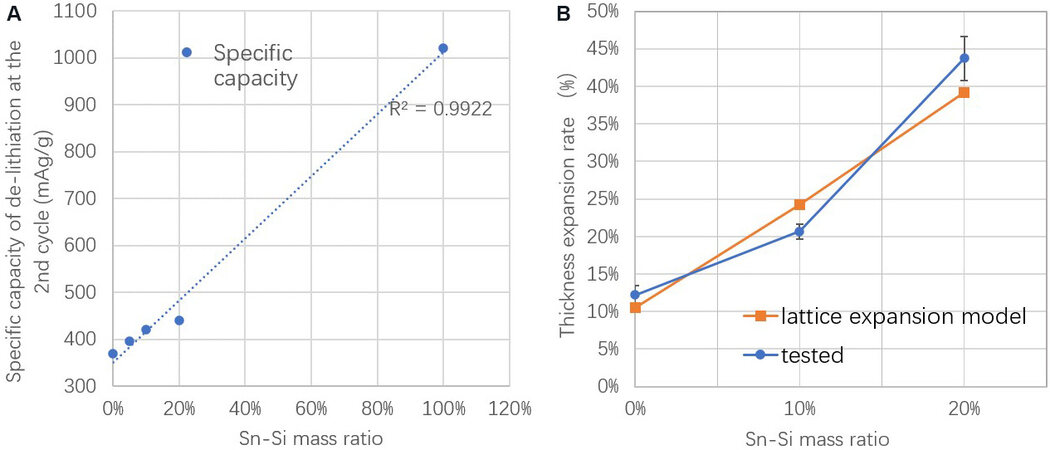
Figure 3. (A) Specific capacity and (B) volume expansion rate of composite anodes as a function of Sn-Si mass ratio.
Volume expansion is a significant concern when using alloy-type active materials. Therefore, the thickness expansions of the electrodes are measured in the composites with 0%, 10% and 20% Sn-Si hybrid, as shown in Figure 3B (the SEM images of the expanded electrodes with Sn-Si ratio from 0% to 20% are provided in Supplementary Figure 1). The pure graphite electrode (0% Sn-Si) displays an expansion of 12.2%, corresponding to its lattice expansion rate multiplied by its volumetric ratio in the electrode[22]. When increasing the Sn-Si content to 10% and 20%, the electrode expansion increases to 20.7% and 43.7%, respectively, thereby approximately following the lattice expansion model. According to the literature, pure Sn and Si are expected to expand by 259% and 312%, respectively, for the ideal lithiation products of Li4.4Sn and Li4.4Si, respectively[6,23], which are impossible for industrial use because of the significant breathing effect. This study shows an important decrease in the volume expansion with the addition of graphite and with appropriate control of the alloy percentage (such as 10%), the total electrode expansion could be controlled to an accepted level for future industrial application.
XRD is used to examine the lithiation products of the composite anodes with different Sn-Si hybrid mass ratios. According to Figure 4, there are three main peaks that represent graphite and its lithiation products of LiC6 (24.1°), LiC12 (25.2°) and LiCX with x > 12 (~26.5°)[22]. Among them, LiC6 and LiC12 are more obviously shown in the anodes with 0% and 10% Sn-Si hybrid. When the Sn-Si ratio increases to 20%, the LiC6 and LiC12 signals became invisible, while the less lithiated graphite compound (LiCX with x > 12) becomes predominant. This might be due to the specific lithium intercalation mechanism that occurs in the graphite-alloy composite anode[30]. Firstly, Li+ intercalation occurs early and intensively in the Sn-Si compound instead of in graphite until reaching a state of charge (SOC) level of ~72%. Then, with increasing SOC, there is a transfer of Li+ from the Sn-Si compound to graphite, leading to a SOC improvement in graphite and a SOC decrease in Sn-Si. However, in the case of 20% Sn-Si, it is likely that the alloy-graphite interfacial resistance restricts such Li+ transfer from Sn-Si to graphite, leading to the disappearance of highly lithiated graphite compounds, such as LiC6 and LiC12. This hypothesis could also be evidenced by the small capacity loss for the anode with 20% Sn-Si ratio [Figure 3A].
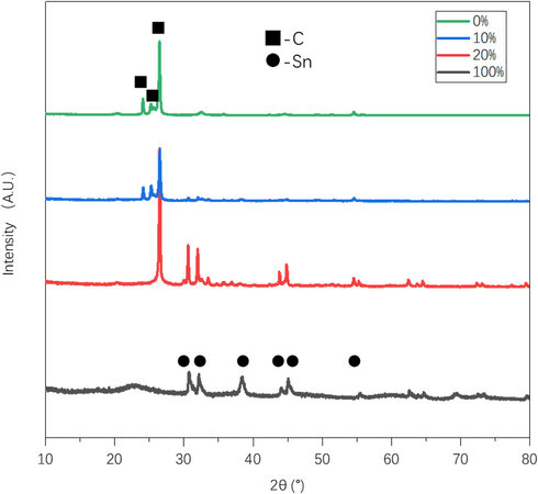
Figure 4. X-ray diffraction patterns of composite anodes after the 1st lithiation with different Sn-Si hybrid percentages.
The lithiation products of the Sn-Si hybrid, mainly Li17Sn4 (30.7°, 32.2°, 38.5°, 44.1°, 45.1° and 55.5°)[6,31,32], become predominantly exhibited in the anode with 20% and 100% Sn-Si. The lithiation product of Si is not present in the XRD pattern since nano silicon tends to transform into an amorphous state after lithiation, as indicated in numerous previous studies[33,34]. Such a gradual switch from graphite-controlled lithiation products to Sn-Si hybrid-controlled lithiation ones accompanied by the increasing Sn-Si content proves the increasing participation of Sn-Si during discharge, which could also explain the higher capacity retention of the composite anode with higher Sn-Si hybrid ratios.
Evaluation of industrial utilization of Sn-Si/C composite anodes compared with conventional graphite anode
According to Figure 5A, the composite anode with 10% Sn-Si leads to a nearly 17% higher specific discharge capacity than the pure graphite anode, thereby confirming the important improvement in the capacity with the addition of the Sn-Si hybrid. However, a lower 1st CE of 75% is observed for the composite anode, compared to 82% of the graphite anode. Both the composite and graphite anodes display a similar tendency in the CEs during the following cycles. In the literature, anodes based on alloy-type active materials are often reported to have a rather low 1st CE because of the severe side reactions during formation[35,36]. This was confirmed by the large amount of gas produced during the formation process of the composite anode pouch cell, whereas the graphite pouch cell had few gas releases, as shown in Figure 6. An intuitive comparison between the as-elaborated Sn-Si/graphite composite and graphite anodes in half cells is displayed in Table 3. Despite a lower 1st CE, the reversible energy density (the reversible discharge capacity multiplied by the pressing density, with the latter given in Table 1) of the composite anode is still 21% higher than that of the conventional graphite anode, making it one of the most promising anode material candidates in terms of energy density.
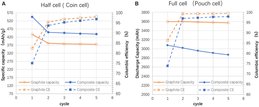
Figure 5. Comparison of discharge capacity and Coulombic efficiency between graphite and composite anodes (Sn-Si hybrid/C = 1:9) in (A) half cell and (B) full cell.
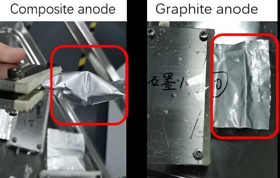
Figure 6. Comparison of gas release content during the formation process between the composite and the graphite cell.
Comparison between the composite anode and the graphite anode in half cells
| Electrode type | Reversible discharge capacity (mAh/g) | 1st CE | Cycling CE (at 5th cycle) | Anode energy density (Ah/L) |
| Sn-Si/graphite composite | 450 | 82% | 98.1% | 810 |
| Graphite | 382 | 75% | 97.0% | 669 |
Despite the higher specific capacity of the composite anode given in the half cell, the discharge capacity of the corresponding full cell using NCM622 as a cathode is 3080 mAh, only 85.6% of that of the graphite cell. This huge capacity loss is highly likely due to the lower 1st CE of the composite anode. In full cells, all the lithium sources come from the cathode, which are of the same quantity for both anodes since both the graphite and composite cells use the same cathode. According to Figure 5B, the composite full cell has a 1st CE of 73.8%, whereas the graphite one is 86.3%. As a result, the theoretical 1st discharge capacity of the composite full cell should be 85.5% (= 73.8%/86.3%) of that of the graphite full cell, extremely close to 85.6%.
The importance of the 1st CE is often ignored in the literature since in most cases, only half cells are used for the electrochemical characterization. In the half cell, lithium metal is used and therefore the capacity loss caused by the 1st CE, which is less than 100%, is not vital since it will be further compensated by the “infinite” lithium sources from the lithium metal for the subsequent cycles. However, in full cells, the capacity of the cell is only derived from the cathode and the 1st capacity loss determines the remaining capacity for the following cycles directly. As a result, both half and full cells are needed for the full understanding of novel Sn-Si/C composite anodes with half cells for an intrinsic 1st CE and specific capacity measurement and full cells for the cycling performance characterization (The extended cycle performance and rate performance of the pouch cells are shown in Supplementary Figure 2).
The SEI compositions of both anodes after five cycles are examined by XPS [Figure 7]. Covalent C-F bonds are regarded as being poor for the ionic conductivity and unfavorable in breaking to form the Li-F bonds, which have good electrical and electrochemical performance. The peak intensity ratio between the C-F and Li-F bonds in the F1s spectrum, as well as the peak intensity of the C-F bonds in the C1s spectrum, is more pronounced for the composite anode than for the graphite anode, indicating a less effective SEI layer formed on the surface of the composite active material. Furthermore, a dominant graphite peak (284.5 eV) and weak C-H/C-N and C-O bonds are observed in the C1s spectrum for the graphite anode, implying a thinner SEI and more slight side reactions occurring in the graphite anode. In addition, C=O peaks, which signify unfavorable side reactions products, like carbonates, are shown to become predominant in the C1s spectra, as well as in the O1s spectra, for the composite anode. The huge growth of the Li-C peak in C1s for the composite anode confirms the previous statement that the SEI formation of the composite anode consumes a large amount of active Li, leading to a poorer coulombic efficiency and a thicker SEI layer than graphite.
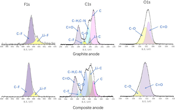
Figure 7. X-ray photoelectron spectroscopy spectra of cycled graphite anode and composite anode (Sn-Si hybrid/C = 1:9).
DISCUSSION
The effectiveness of the as-elaborated Sn-Si/C composite anode in comparison with its analogues is shown in Table 4. The feasibility of an anode for industrial use can be approximated in terms of the reversible capacity, the 1st CE, the cycling CE and the compatibility with current battery processes. This study prepared novel Sn-Si/graphite composite anodes with a comparatively high reversible capacity of 450 mAh g-1, a highest 1st CE of 75%, a good cycling CE of 98% and good compatibility with current battery processes, making it closer for the industrialization of alloy-based active materials. For the further applications of Sn-Si hybrid/C composite anodes, pre-lithiation is needed in order to assure the correct release of the high specific capacity of the composite anodes in full batteries. Moreover, with better control of the synthesis of the Sn-Si hybrid active materials, the cycling CE could be improved to over 99% (currently under study), which would further promote the application of such composite anodes in long cycle applications, like electric vehicles.
Comparison of as-elaborated Sn-Si/C composite anode with analogue active materials from the literature
| Ref. | Active material morphology | Sn-Si hybrid mass ratio | Reversible discharge capacity mAh g-1 | 1st CE | Average cycling CE | Compatible with industrial battery processes |
| This work | Sn-Si hybrid/graphite composite | 10% | 450 | 75% | 98% | Yes |
| Fang et al.[13] | Sn-P coated graphite | 30% | 370 | 47% | 99.9% | Yes |
| Wang et al.[12] | Ball-milled Sn /graphite composite | 20% | ~500 | 50% | 97.5% | Yes |
| Ding et al.[18] | Sn/graphene composite nanosheet | 20% | 539 | 65% | 92% | No |
CONCLUSIONS
Composite anodes using a Sn-Si hybrid and graphite binary active system are successfully elaborated in this study. Morphological characterization confirms the uniform distribution of the two types of active materials within the electrode. The charge-discharge profiles of all composite anodes display a combination of both the Sn-Si hybrid and graphite reaction characteristics with a clear tendency to approach the profile of their predominant constituent. The capacity retention data also confirm the effectiveness of the composite anodes with a quasi-linear relationship between the capacity retention and the mass ratio of the Sn-Si hybrid. The XRD results show a gradual switch from graphite-dominant lithiation products into Sn-Si hybrid-dominant lithiation products in the composite anode with increasing Sn-Si hybrid content, implying changes in the predominant lithiation reactions. The electrochemical performance and expansion rate are characterized and a Sn-Si ratio of 10% is recommended for an industrial acceptable expansion rate of 20.7% (12.2% for pure graphite anode expansion) and a good capacity release (450 mAh g-1).
Both half and full cells are elaborated to fully investigate the Sn-Si hybrid/C composite anodes in comparison with the conventional graphite anode, revealing the importance of the 1st CE that leads to a lower discharge capacity in the full cells despite a better specific capacity exhibited in the half cells. Such a low 1st CE is due to the severe side reactions occurring during the formation process of the battery using the Sn-Si hybrid-participated anode, confirming by both photographs and XPS patterns. Overall, the Sn-Si/C composite anode elaborated in this study possesses a high reversible capacity (450 mAh g-1), a comparatively promising 1st CE (75%) and stable cycling (CE > 98%) simultaneously, making it one of the most promising Sn-Si hybrid/C composite anodes for industrial use. With the further improvement of the 1st CE by pre-lithiation technologies and the cycling CE by a careful control of the active material synthesis, the real application of such anodes in electric vehicle applications would likely become a reality.
DECLARATIONS
Authors’ contributionsConception of the study and wrote the manuscript: Shao Y, Huang X
Material support: Jin Z
Data analysis and technical support: Li J
Performed experience and data acquisition: Meng Y
Availability of data and materialsNot applicable.
Financial support and sponsorshipThis work was financed by China Postdoctoral Science Foundation (Grant number: 2021M700928), Guangdong Basic and Applied Basic Research Foundation (Grant number: 2021A1515110068) and National Key R&D Program of China (Grant number: 2019YFA0705100). The authors would like to acknowledge Taiguo BAI, Dr. Yuanjie Zhan, Haicong Liang, engineers from the Songshan Lake Materials Laboratory, for their help in the material characterization and the pouch cell assembly.
Conflicts of interestAll authors declared that there are no conflicts of interest.
Ethical approval and consent to participateNot applicable.
Consent for publicationNot applicable.
Copyright© The Author(s) 2022.
Supplementary MaterialsREFERENCES
1. Marom R, Amalraj SF, Leifer N, Jacob D, Aurbach D. A review of advanced and practical lithium battery materials. J Mater Chem 2011;21:9938.
2. Zhang W. A review of the electrochemical performance of alloy anodes for lithium-ion batteries. J Power Sources 2011;196:13-24.
3. Tao W, Wang P, You Y, et al. Strategies for improving the storage performance of silicon-based anodes in lithium-ion batteries. Nano Res 2019;12:1739-49.
4. Whiteley JM, Kim JW, Kang CS, Cho JS, Oh KH, Lee S. Tin networked electrode providing enhanced volumetric capacity and pressureless operation for all-solid-state Li-ion batteries. J Electrochem Soc 2015;162:A711-5.
5. Whiteley JM, Kim JW, Piper DM, Lee S. High-capacity and highly reversible silicon-tin hybrid anode for solid-state lithium-ion batteries. J Electrochem Soc 2015;163:A251-4.
6. Courtney IA, Dahn JR. Electrochemical and in situ X-ray diffraction studies of the reaction of lithium with tin oxide composites. J Electrochem Soc 1997;144:2045-52.
7. Yan Y, Ben L, Zhan Y, Huang X. Nano-Sn embedded in expanded graphite as anode for lithium ion batteries with improved low temperature electrochemical performance. Electrochimica Acta 2016;187:186-92.
8. Jin Z, Ben L, Yu H, Zhao W, Huang X. A facile method to synthesize 3D structured Sn anode material with excellent electrochemical performance for lithium-ion batteries. Prog Nat Sci Mater Int 2020;30:456-60.
9. Kierzek K, Machnikowski J, Béguin F. Towards the realistic silicon/carbon composite for Li-ion secondary battery anode. J Appl Electrochem 2015;45:1-10.
10. Otero M, Heim C, Leiva EPM, Wagner N, Friedrich A. Design-considerations regarding silicon/graphite and tin/graphite composite electrodes for lithium-ion batteries. Sci Rep 2018;8:15851.
11. Wang G, Ahn J, Lindsay M, et al. Graphite-Tin composites as anode materials for lithium-ion batteries. J Power Sources 2001;97-98:211-5.
12. Wang G, Yao J, Ahn J, Liu H, Dou S. Electrochemical properties of nanosize Sn-coated graphite anodes in lithium-ion cells. J Appl Electrochem 2004;34:187-90.
13. Fang T, Hsiao L, Duh J, Sheen S. A novel composite negative electrode consist of multiphase Sn compounds and mesophase graphite powders for lithium ion batteries. J Power Sources 2006;160:536-41.
14. Guo B, Shu J, Tang K, Bai Y, Wang Z, Chen L. Nano-Sn/hard carbon composite anode material with high-initial coulombic efficiency. J Power Sources 2008;177:205-10.
15. Pol VG, Wen J, Miller DJ, Thackeray MM. Sonochemical deposition of Sn, SnO2 and Sb on spherical hard carbon electrodes for Li-Ion batteries. J Electrochem Soc 2014;161:A777-82.
16. Shao Y, Guizani C, Grosseau P, Chaussy D, Beneventi D. Use of lignocellulosic materials and 3D printing for the development of structured monolithic carbon materials. Compos. Part B Eng 2018;149:206-15.
17. Mo R, Tan X, Li F, et al. Tin-graphene tubes as anodes for lithium-ion batteries with high volumetric and gravimetric energy densities. Nat Commun 2020;11:1374.
18. Ding S, Cheng W, Zhang L, et al. Organic molecule confinement reaction for preparation of the Sn nanoparticles@graphene anode materials in Lithium-ion battery. J Colloid Interface Sci 2021;589:308-17.
19. Nakai H, Kubota T, Kita A, Kawashima A. Investigation of the solid electrolyte interphase formed by fluoroethylene carbonate on Si electrodes. J Electrochem Soc 2011;158:A798-801.
20. Moulder JF, Stickle WF, Sobol PE, Bomben KD. . Handbook of X-ray photoelectron spectroscopy. Minnesota: Perkin-Elmer Corporation; 1992.
21. Shao Y, Guizani C, Grosseau P, Chaussy D, Beneventi D. Biocarbons from microfibrillated cellulose/lignosulfonate precursors: a study of electrical conductivity development during slow pyrolysis. Carbon 2018;129:357-66.
22. Zhang N, Tang H. Dissecting anode swelling in commercial lithium-ion batteries. J Power Sources 2012;218:52-5.
23. Kasavajjula U, Wang C, Appleby AJ. Nano- and bulk-silicon-based insertion anodes for lithium-ion secondary cells. J Power Sources 2007;163:1003-39.
24. Kalnaus S, Rhodes K, Daniel C. A study of lithium ion intercalation induced fracture of silicon particles used as anode material in Li-ion battery. J Power Sources 2011;196:8116-24.
25. Schiele A, Breitung B, Mazilkin A, et al. Silicon nanoparticles with a polymer-derived carbon shell for improved lithium-ion batteries: Investigation into volume expansion, gas evolution, and particle fracture. ACS Omega 2018;3:16706-13.
26. Kobayashi N, Inden Y, Endo M. Silicon/soft-carbon nanohybrid material with low expansion for high capacity and long cycle life lithium-ion battery. J Power Sources 2016;326:235-41.
27. Sheng Y, Fell CR, Son YK, Metz BM, Jiang J, Church BC. Effect of calendering on electrode wettability in lithium-ion batteries. Front Energy Res 2014;2:56.
28. Lu X, Daemi SR, Bertei A, et al. Microstructural evolution of battery electrodes during calendering. Joule 2020;4:2746-68.
29. Lu X, Bertei A, Finegan DP, et al. 3D microstructure design of lithium-ion battery electrodes assisted by X-ray nano-computed tomography and modelling. Nat Commun 2020;11:2079.
30. Moon J, Lee HC, Jung H, et al. Interplay between electrochemical reactions and mechanical responses in silicon-graphite anodes and its impact on degradation. Nat Commun 2021;12:2714.
31. Courtney IA, Tse JS, Mao O, Hafner J, Dahn JR. Ab initio calculation of the lithium-tin voltage profile. Phys Rev B 1998;58:15583-8.
32. Im HS, Cho YJ, Lim YR, et al. Phase evolution of tin nanocrystals in lithium ion batteries. ACS Nano 2013;7:11103-11.
33. Wu R, Liu X, Zheng Y, et al. Unveiling the intrinsic reaction between silicon-graphite composite anode and ionic liquid electrolyte in lithium-ion battery. J Power Sources 2020;473:228481.
34. Limthongkul P, Jang Y, Dudney NJ, Chiang Y. Electrochemically-driven solid-state amorphization in lithium-metal anodes. J Power Sources 2003;119-121:604-9.
35. Forney MW, Ganter MJ, Staub JW, Ridgley RD, Landi BJ. Prelithiation of silicon-carbon nanotube anodes for lithium ion batteries by stabilized lithium metal powder (SLMP). Nano Lett 2013;13:4158-63.
Cite This Article
Export citation file: BibTeX | RIS
OAE Style
Shao Y, Jin Z, Li J, Meng Y, Huang X. Evaluation of the electrochemical and expansion performances of the Sn-Si/graphite composite electrode for the industrial use. Energy Mater 2022;2:200004. http://dx.doi.org/10.20517/energymater.2021.27
AMA Style
Shao Y, Jin Z, Li J, Meng Y, Huang X. Evaluation of the electrochemical and expansion performances of the Sn-Si/graphite composite electrode for the industrial use. Energy Materials. 2022; 2(1): 200004. http://dx.doi.org/10.20517/energymater.2021.27
Chicago/Turabian Style
Shao, Ying, Zhou Jin, Jin Li, Yemin Meng, Xuejie Huang. 2022. "Evaluation of the electrochemical and expansion performances of the Sn-Si/graphite composite electrode for the industrial use" Energy Materials. 2, no.1: 200004. http://dx.doi.org/10.20517/energymater.2021.27
ACS Style
Shao, Y.; Jin Z.; Li J.; Meng Y.; Huang X. Evaluation of the electrochemical and expansion performances of the Sn-Si/graphite composite electrode for the industrial use. Energy Mater. 2022, 2, 200004. http://dx.doi.org/10.20517/energymater.2021.27
About This Article
Copyright

Data & Comments
Data


 Cite This Article 21 clicks

 Like This Article 30
likes
Like This Article 30
likes


Comments
Comments must be written in English. Spam, offensive content, impersonation, and private information will not be permitted. If any comment is reported and identified as inappropriate content by OAE staff, the comment will be removed without notice. If you have any queries or need any help, please contact us at support@oaepublish.com.