
Lithium molybdate composited with carbon nanofibers as a high-capacity and stable anode material for lithium-ion batteries


Abstract
Transition metal molybdates have been studied as anode materials for high-performance lithium-ion batteries, owing to their high theoretical capacity and low cost, as well as the multivalent states of molybdenum. However, their electrochemical performance is hindered by poor conductivity and large volume changes during charge and discharge. Here, we report lithium molybdate (Li2MoO4) composited with carbon nanofibers (Li2MoO4@CNF) as an anode material for lithium-ion batteries. Li2MoO4 shows a shot-rod nanoparticle morphology that is tightly wound in the fibrous CNF. Compared with bare Li2MoO4, the Li2MoO4@CNF composite demonstrates superior high specific capacity and cycling stability, which are attributed to the reversible Li-ion intercalation in the LixMoyOz amorphous phase during charge and discharge. The capacity of the Li2MoO4@CNF anode material can reach 830 mAh g-1 in the second cycle and 760 mAh g-1 after 100 cycles at a charge/discharge current density of 100 mA g-1, which is much better than the bare Li2MoO4. This work provides a simple method to prepare a high-capacity and stable lithium molybdate anode material for lithium-ion batteries.
Keywords
INTRODUCTION
Lithium (Li)-ion batteries are recognized as green power sources for next-generation battery related applications, such as portable electronic devices, electric vehicles, and stationary energy storage systems[1-3]. At present, commercialized Li-ion battery anodes are mainly composed of carbonaceous materials, in which graphite is the major active component with a theoretical specific capacity of ~372 mAh g-1[4]. However, higher specific capacity materials are sought to improve the energy density of Li-ion batteries. Typical Mo-based oxides, such as MoO2 and MoO3, exhibit higher theoretical specific capacities than sulfides and selenides[5-10]. Among them, MMoO4 (M = Fe, Ni or Mn)[11-14] materials have gained significant attention because of their higher specific capacities and multivalent states. Nevertheless, due to the relatively low conductivity and conversion reactions occurring at lower voltages, these metal oxides cannot maintain their specific capacities during long cycling, resulting in fast capacity decay and poor cycling performance[15,16].
In general, metal oxides can be modified with a special morphology or through compounding with other materials[17,18]. Chen et al. synthesized porous hollow Co3O4 microfibers by a template method, which showed a capacity of 787.6 mAh g-1 at a current density of 100 mA g-1 after 200 cycles[19]. This unique morphology enabled the material to have a large contact surface area and sufficient void space in the electrochemical reaction process. Tian et al. combined Bi2Mo3O12 with a Ti3C2 MXene, which reached a specific capacity of 227 mAh g-1 at a high current density of 2.5 A g-1 after 1000 cycles[20]. The Ti3C2 MXene-supported substrate improved the structural stability and electronic conductivity of the electrode materials. Recently, lithium molybdate (Li2MoO4) has been studied as an anode material for Li-ion batteries because of its simple synthesis method and high specific capacity[21-24]. The studies have confirmed that the combination of Li2MoO4 and carbon can effectively reduce the volume expansion in the Li-ion extraction/insertion processes, and thus, its electrochemical performance can be improved. Liu et al. selected citric acid as a carbon source to coat Li2MoO4 nanotubes via a sol-gel method in which a conversion reaction mechanism of Li2MoO4 was proposed[25]:
Li2MoO4 + 6Li+ +6e- → Mo + 4Li2O (1)
Mo + yLi2O ↔ LixMoOy(O - phase) + (2y-x)Li+ +(2y - x)e- (2)
In this work, we explore Li2MoO4 composited with carbon nanofibers (CNFs) as an anode for Li-ion batteries. A simple sol-gel synthesis route is introduced to make nanoparticles of Li2MoO4 decorated in a CNF network. Various characterization techniques are employed to analyze the structure and composition of the composite material. So far, few literature works have explored the lithium storage mechanism of Li2MoO4 as an anode material. Through in situ X-ray diffraction (XRD), ex situ X-ray photoelectron spectroscopy (XPS) analysis, and electrochemical cyclic voltammetry of charge and discharge examinations, we propose a reaction mechanism that indicates that the Li2MoO4@CNF material experiences reversible Li-ion intercalation reactions starting from the second charge and discharge cycle. The Li2MoO4@CNF composite anode material delivers an initial charge capacity of 1294 mAh g-1 at 50 mA g-1 and retains a capacity of 290 mAh g-1 upon prolonged cycling (800 cycles) at a 1 A g-1 charge/discharge current density. This work demonstrates the superior performance of the Li2MoO4@CNF anode material for Li-ion batteries.
EXPERIMENTAL
Synthesis of Li2MoO4@CNF materials
CNFs were first functionalized using 60 mL of a 34 wt.% nitric acid solution (analytical reagent, Sinopharm) added to 200 mg of commercial CNF materials (OCSiAl). The mixture was sealed in a Teflon-lined stainless-steel autoclave for hydrothermal treatment at 140 °C for 6 h. After that, the precipitate from the autoclave was transferred to a high-speed centrifuge, centrifuged three times, and washed several times with ethanol and deionized water until the pH became neutral. The obtained functionalized CNF were then dried in a vacuum at 80 °C for 12 h. Li2MoO4@CNF composites were synthesized by a simple and feasible sol-gel method. Typically, 66 mg of functionalized CNF were ultrasonically dispersed in 30 mL of an alcohol solvent, with 30 mL of an aqueous solution of 0.754 g of Li2CO3 (99%, Sigma-Aldrich) and 1.4467 g of MoO3 (99.9%, Shanghai Macklin Biochemical Co., Ltd.) then added. Afterwards, the mixture was fully stirred at
Materials characterization
The crystallographic structures of the as-prepared materials were characterized by XRD on a Bruker automatic diffractometer with Cu-Kα radiation. The LMO and LMO@CNF materials were characterized by Raman spectroscopy on a micro confocal Raman spectrometer (Horiba). The carbon content within the LMO@CNF material was determined by thermogravimetric (TG) analysis on a thermal analyzer (Hitachi) in air at a temperature range between room temperature and 700 °C. The morphology and structure of the prepared samples were observed using field emission scanning electron microscopy (Hitachi), transmission electron microscopy (TEM, FEI) and high-resolution spherical aberration corrected transmission electron microscopy (AC-TEM, FEI), respectively. XPS (Thermo Fisher) measurements were used for characterization of the chemical valence states of the materials and electrode surfaces. All XPS spectra were calibrated with reference to the binding energy of the C 1s peak at 284.8 eV.
Electrochemical measurements
The working electrode was composed of the active material (80 wt.%), Super-P (10 wt.%), and polyvinylidene fluoride (10 wt.%). The mixture was fully stirred in an N-methyl-2 pyrrolidone solvent for
RESULTS AND DISCUSSION
Figure 1A illustrates the synthesis process of the LMO@CNF composite materials. Proportional amounts of Li2CO3 and MoO3 were added to the dispersed functionalized CNF alcohol solvent, which could be evenly and fully mixed by a simple sol-gel method. The lithium molybdate crystal structure is composed of corner-linked, slightly distorted LiO4 and MoO4 tetrahedra, which form a three-dimensional network with a narrow open channel along c-axis[26]. Lithium molybdate has a hexagonal structure with the space group R-3H, which exhibits the transverse (⊥c) directions {0001} surfaces and the parallel (||c) directions {1010} surfaces shown in Figure 1H[22]. Thus, it can be seen from the SEM image of the unannealed LMO that LMO exists in the form of rods [Figure 1B]. After annealing in an argon atmosphere at 400 °C to remove the residual components, the surface and ends of LMO particles appear to be hexagonal [Figure 1C], with the same occurring for the unannealed LMO@CNF [Figure 1D] and annealed LMO@CNF [Figure 1E]. The TEM images show that the CNF are wrapped around LMO, with small particles embedded in the CNF network
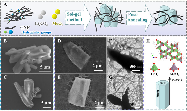
Figure 1. (A) Schematic of the synthesis of LMO@CNF composite material. (B) SEM images of unannealed LMO and (C) annealed LMO. (D) SEM images of unannealed LMO@CNF and (E) annealed LMO@CNF. (F) TEM images of unannealed LMO@CNF and (G) annealed LMO@CNF. (H) Crystal structure of annealed LMO.
The high-resolution transmission electron microscopy (HRTEM) image in Figure 2A displays the high graphitization of CNF due to the distinct lattice stripes. The orange dotted line in Figure 2B shows the clear contour of a lithium molybdate rod, together with a zoomed-in HRTEM view of a selected region (squared in solid green lines), where obvious lattice stripes of nanoparticles can be observed [Figure 2C]. As shown in Figure 2D, the CNF coverage can be clearly seen in the left area, with dark nanoparticles of a particle size of ~5 nm also observed. Lattice fringes (squared in solid purple lines) with the corresponding d-space distances of 0.42 and 0.29 nm can be indexed to the (211) and (113) planes of the LMO [Figure 2E], respectively. Figure 2F displays the high-angle annular dark field (HAADF) scanning TEM image of LMO@CNF coupled with energy-dispersive spectrometer (EDS) mappings, which reveal the distribution of the C, Mo and O elements, which verify the combination of LMO rods and CNF.
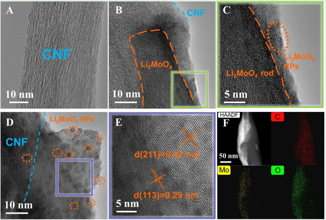
Figure 2. HRTEM images of (A) CNF, (B) LMO@CNF, and (C) enlarged view of the area in (B). HRTEM image of (D) LMO@CNF and (E) enlarged lattice fringes in (D). (F) HAADF-STEM image of LMO@CNF and EDS mappings showing the distribution of C, Mo, and O elements.
The XRD characterization of the two samples shown in Figure 3A is consistent with the hexagonal structure of Li2MoO4 (PDF: 12#0763). Lithium molybdate has typical vibrational frequencies of tetrahedral transition metal oxides (MeO4 type). Four vibration mode peaks of lithium molybdate can be seen in the Raman spectra [Figure 3B], which are related to the asymmetric bending (ν4) and asymmetric stretching vibration
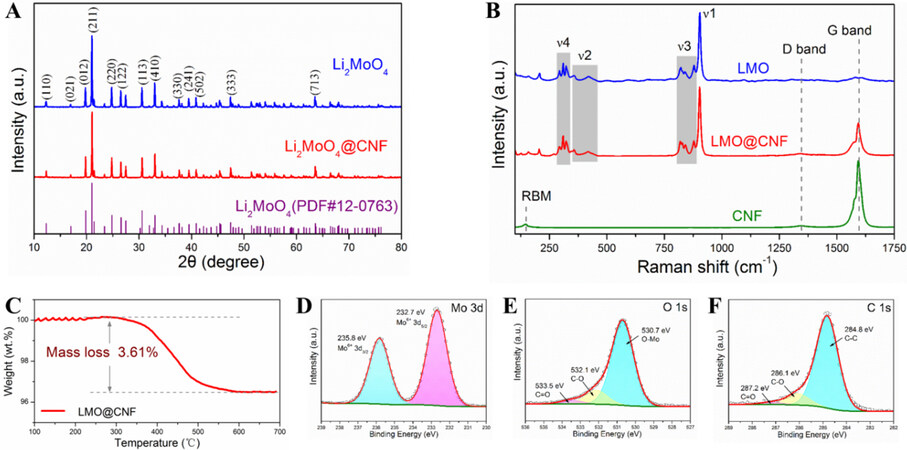
Figure 3. (A) XRD patterns and (B) Raman spectra compared with CNF. (C) TG curve of LMO@CNF powder heated in air. (D) Mo 3d, (E) O 1s, and (F) C 1s X-ray photoelectron spectra of LMO@CNF. XRD: X-ray diffraction.
According to the TG analysis in Figure 3C, the slight fluctuation from 100 to 250 °C is due to the evaporation of residual water. The main weight loss from 250 °C to over 600 °C is due to the oxidation of carbon materials in air and the CNF content within the LMO@CNF is determined to be 3.61 wt.%. XPS was carried out on the LMO@CNF powder to study the chemical environments of the Mo, O, and C elements, as plotted in Figure 3D-F, respectively. The hexavalent Mo cations of the LMO@CNF material are verified by binding energies of Mo 3d3/2 (235.8 eV) and Mo 3d5/2 (232.7 eV) in Figure 3D. According to the fitting patterns, the O 1s peak can be deconvoluted to one dominant O-Mo contribution at 530.7 eV, together with two weak peaks from the C-O bond at 532.1 eV and the C=O bond at 533.5 eV [Figure 3E]. The C 1s peak can be decomposed into a C-C bond (284.8 eV), a C-O bond (286.1 eV), and a C=O bond (287.2 eV) [Figure 3F].
The lithium storage performance of the LMO@CNF anode material was evaluated by CV in a voltage range of 0.01-3.0 V vs. Li+/Li. In Figure 4A-C, the CV profiles of the LMO, CNF, and LMO@CNF anodes are shown with the initial four cycles recorded at a scanning rate of 0.1 mV s-1. As shown by the CV characteristics of the LMO and CNF materials, the initial reduction peak at 1.11 V in the first discharge of the LMO@CNF shown in Figure 4C is attributed to the Li-ion intercalation process that forms Li2+xMoO4. The subsequent irreversible peak at 0.63 V corresponds to the formation of a solid electrolyte interphase (SEI) layer[29]. By comparing the initial cycles (black curves) of the three materials between 0.01 and 0.5 V in Figure 4A-C, it can be found that the curves in Figure 4B and C show some small reduction peaks, indicating that the lithiation process of CNF can also occur at low potentials. In the first charge process, the oxidation peak of LMO@CNF at 1.26 V may be due to the formation of oxidized molybdenum in a high valence state. Compared with the oxidation peak of LMO at a more positive potential of 1.56 V [Figure 4A], the 1.26 V peak of LMO@CNF may be attributed to the CNF conductive network, which allows the molybdenum to be oxidized more easily. The oxidation peak at 2.46 V is attributed to the delithiation process of CNF, as shown in Figure 4B and C. Repeatable CV curves are obtained in the next 2nd to 4th cycles [Figure 4C], showing reversible electrochemical performance of the LMO@CNF anode. The dominant reduction peak is located at 0.19 V, which can be attributed to the reduction of amorphous Li-Mo-O compounds to Mo metal. Compared with the reduction peak of LMO at 0.01 V, the earlier appearance of reduction peak at the higher potential of LMO@CNF may be due to the increased conductivity from CNF causing deep lithiation.
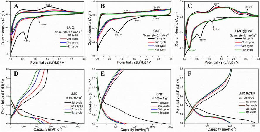
Figure 4. Electrochemical CV profiles of (A) LMO, (B) CNF, and (C) LMO@CNF anodes at a scanning rate of 0.1 mV s-1. Charge/discharge curves at a current density of 100 mA g-1 of (D) LMO, (E) CNF, and (F) LMO@CNF anodes. CV: Cyclic voltammetry.
Figure 4D-F display the charge/discharge curves in the first four cycles of the three anode materials at a current density of 100 mA g-1 between 0.01 and 3.0 V vs. Li+/Li, which are consistent with the CV observations. The LMO@CNF anode material further shows superior high-rate performance by delivering specific capacities of 854, 804, 731, 645, 533, 390, and 274 mAh g-1 at the corresponding current densities of 50, 100, 250, 500, 1000, 1500, and 2000 mA g-1, respectively, much higher than the capacities displayed by the LMO and CNF anodes, as compared in Figure 5A. In particular, the specific capacity reaches ~900 mAh g-1 when the LMO@CNF anode is cycled back to a low current density of 50 mA g-1 after high-rate steps. Furthermore, the cycling performance at different current densities of 100, 500, and 1000 mA g-1 of the three materials is given in Figure 5B-D. The LMO@CNF anode can deliver initial discharge and charge capacities of 1,218 and 831 mAh g-1 at a low current density of 100 mA g-1. The initial Coulombic efficiency is ~68.2%, and the irreversible capacity loss is mainly due to the formation of the SEI layer and the irreversible conversion reaction of the LMO. In contrast, the initial Coulombic efficiency of the LMO anode is ~54.2%, which shows that the composite with a carbon material can reduce the loss of lithium ions and effectively improve the first cycle efficiency of the LMO anode material. It should be emphasized that after 100 cycles, the LMO@CNF anode can still maintain a specific capacity of 761 mAh g-1, much higher than the specific capacities exhibited by the LMO and CNF anodes, as shown in Figure 5B.
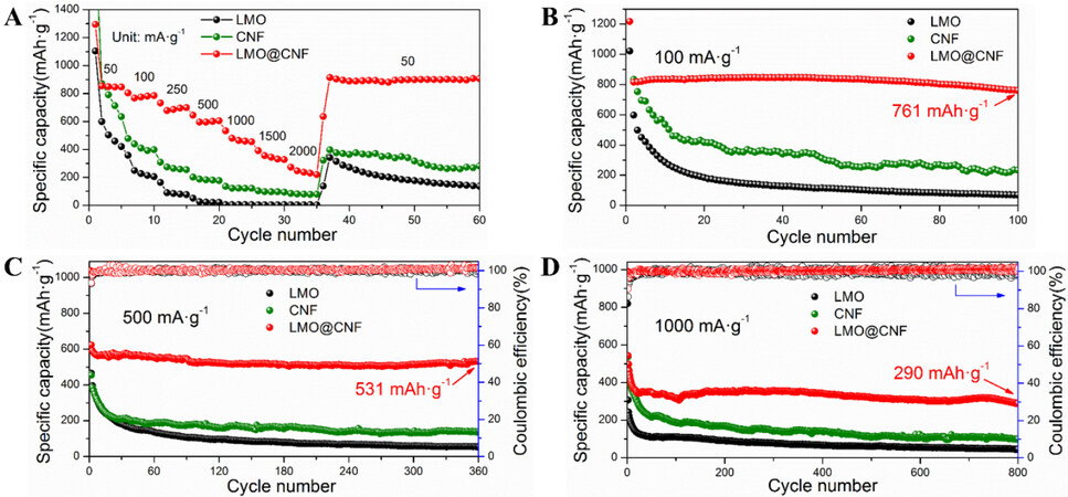
Figure 5. (A) Rate performance of LMO, CNF, and LMO@CNF anodes. Cycling performance at current densities of (B) 100, (C) 500, and (D) 1000 mA g-1 of the three materials.
The LMO@CNF anode displays a similar excellent electrochemical performance at a higher current density of 500 mA g-1, in which a 531 mAh g-1 specific capacity is exhibited after 360 cycles [Figure 5C]. Under the same current density of 500 mA g-1, LMO and CNF anodes only show specific capacities of 55 and 139 mAh g-1 after 360 cycles, respectively. The LMO@CNF anode also demonstrates good cycling performance [Figure 5D], with a specific capacity of 290 mAh g-1 preserved after 800 cycles at a high current density of 1000 mA g-1. The rate and cycling performances of the LMO@CNF anode are significantly better than those of LMO and CNF anodes alone, which is attributed to the synergistic effect of LMO with CNF. The results indicate that in the charge and discharge processes, the CNFs provide a conductive network for broken LMO particles as connected islands, so that the capacities of all the LMO particles can be delivered. Furthermore, this work indicates the superior electrochemical performance of Li2MoO4 over other literature work, with the relevant comparisons placed in Supplementary Figure 1 and Supplementary Table 1.
EIS was carried out for the LMO and LMO@CNF materials before cycling and after 200 cycles, as shown in Figure 6. Through fitting of the experimental EIS data using the equivalent circuit model in Figure 6D, the charge transfer resistance (Rct) of 93.3 Ω is obtained for the LMO anode before cycling, while the Rct of the LMO@CNF is much lower at 48.5 Ω, [Figure 6A], indicating its higher electron transfer rate at the electrode interface. The Li-ion diffusion rate can be calculated by[30,31]:
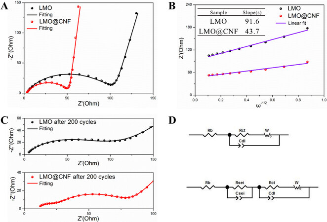
Figure 6. Electrochemical impedance spectra and fitting plots of LMO and LMO@CNF anodes (A) before cycling, (B) impedance response to frequency, (C) after 200 cycles, and (D) corresponding equivalent circuits.
D0 = 2n-4A-2F-4C-2R2T2σ-2 (3)
where D0 is the diffusion coefficient of Li+ and σ is the slope, which could be obtained by the linear fitting of Z’ and ω-1/2 in the low-frequency region [Figure 6B]. When the other quantities are constant, the diffusion coefficient depends on the variable σ. It could be calculated that the Li+ diffusion coefficient ratio of the LMO@CNF to LMO is 4.39, indicating that the LMO@CNF is a better diffusion material for Li+ due to the conductive CNF network providing better transmission channels. Interestingly, the LMO@CNF anode after 200 cycles shows two distinct semicircles in the Nyquist plot [Figure 6C], corresponding to the charge transfer resistance in the high-frequency region and the SEI layer in the medium-frequency region, indicating the newly formed SEI layer after 200 cycles. The CV test results at different scanning rates show that the DLi+of LMO@CNF is higher than that of LMO, which is consistent with that measured by EIS, proving that CNF can effectively improve the Li-ion migration in the material [Supplementary Figure 2 and Supplementary Table 2].
In order to understand the phase transitions and structural evolutions during the cyclic lithiation/delithiation of the LMO@CNF anode material, in situ XRD measurements were performed under a current density of 100 mA g-1. Supplementary Figure 3 shows the charge/discharge curves of the LMO@CNF anode in the first cycle, together with the contour maps of the XRD characteristic reflections of the LMO component. During the initial discharge, the intensity of the XRD peaks of LMO gradually decreases. These peaks disappeared completely when the initial discharge reached ~1 V. This corresponds to the 1.11 V reduction peak of the CV curve from the LMO@CNF anode [Figure 4C], meaning that the starting Li2MoO4 crystals were converted into amorphous substances. To verify the structural changes in the reaction process, ex situ XRD measurements were carried out on the LMO@CNF material. The electrode samples of the LMO@CNF were taken out of the coin cells in the glove box after being scanned to 0.01 V and sealed in plastic bags for ex situ XRD examination. Another sample charged to 3.0 V after three cycles was also made and tested. It was found that a weak diffraction peak appeared at 32.5° when the electrode was discharged to 0.01 V and discharged/charged after three cycles [Supplementary Figure 4]. However, this peak cannot match the standard PDF card of any substance.
In the investigation of the LMO@CNF material structure after the conversion reaction and its impact on the electrochemical performance, the LMO@CNF material was examined by TEM and HAADF-STEM after being discharged to 0.01 V. Figure 7A shows the LMO particles and CNF. Figure 7B displays the HAADF-STEM images of LMO@CNF framed in dark blue and light blue lines from Figure 7A, coupled with EDS mappings that reveal the distribution of the C, Mo, and O elements. The material is described as a Li-Mo-O compound. Figure 7D shows an enlarged view from the green line region in Figure 7C, showing many small black crystalline grains anchored on the carbon layer. The lattice fringes of the nanoparticles are shown in both Figure 7E (squared in purple lines) and F(squared in light blue lines). According to the Bragg equation, the d-space distance of 0.27 nm could match the diffraction peak at 32.5° obtained by ex situ XRD measurements [Supplementary Figure 4]. This means that this Li-Mo-O compound is likely to exist in the form of nanocrystallites, and as a result, its size is too small to detect by XRD. Furthermore, the d-space distance of 0.36 nm can be indexed to the (011) plane of Li0.98MoO2. According to the literature[32-35], Li0.98MoO2 can be converted to Mo and Li2O at low potentials. Combined with the comparison of the CV curves in Figure 4A and C above, we can postulate that the reaction mechanism in the first discharge process of the LMO and LMO@CNF anodes should be a three-step reaction of “lithiation, phase transition and conversion”:
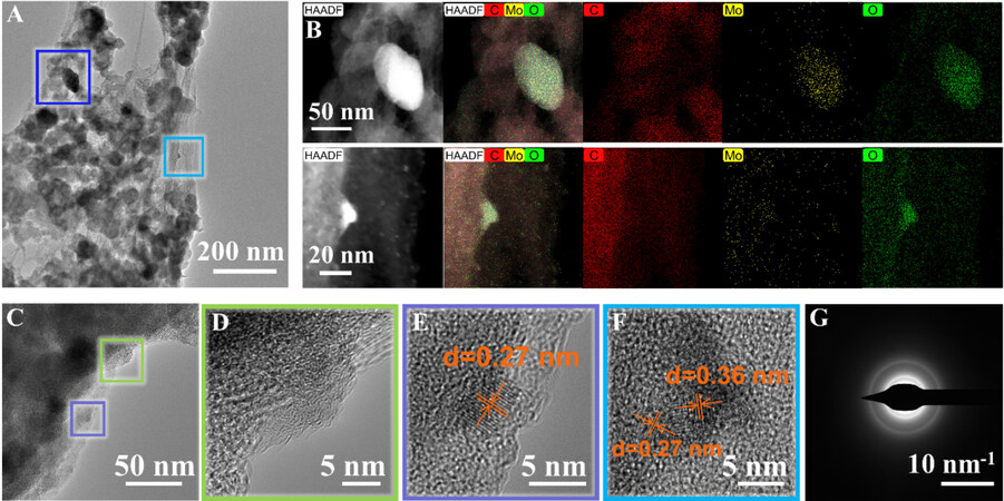
Figure 7. (A) TEM image of LMO@CNF anode material after being discharged to 0.01 V at a current density of 100 mA g-1. (B) HAADF-STEM images and EDS mappings showing the distribution of the C, Mo, and O elements. (C) Additional TEM image and enlarged areas of HRTEM images in (D), (E) and (F). (G) SAED pattern of LMO@CNF material. SAED: Selected area electron diffraction; HAADF: high-angle annular dark field.
Li2MoO4 + δLi+ → Li2+δMoO4 (Lithiation) (4)
Li2+δMoO4 + (6 – δ) Li+ → (Li0.98MoO2) → Mo + 4Li2O (Phase transition and conversion) (5)
The reaction in the first charge process of the LMO and LMO@CNF anodes is as follows:
Mo + 4 Li2O → (8 – δ) Li+ + LiδMo8-δO4 (or LixMoyOz or Li –Mo – O) (6)
In the following charge and discharge processes, the anode material goes through Li-Mo-O to Mo + Li2O reversible reactions, as described in Equation 6. Figure 7G shows the selected area electron diffraction (SAED) pattern of the LMO@CNF material. The diffraction spots are almost invisible, indicating that the material is amorphous after being discharged to 0.01 V, which is consistent with the above observation.
Ex situ XPS was carried out on the LMO and LMO@CNF anodes after being discharged to 0.01 V and charged to 3.0 V [Figure 8], in an attempt to study the chemical environment of the Mo and O elements. The electrodes were taken out of the cells in the glove box and kept in a vacuum to prevent oxidation in air. The X-ray photoelectron spectra of the LMO and LMO@CNF anodes after being discharged to 0.01 V are shown in Figure 8A and B. There are Mo spectra at various valence states, illustrating the co-existence of mixed molybdenum compounds in the reaction process. We believe that the LixMoyOz or Li-Mo-O substance exists in both the reaction processes of the LMO and LMO@CNF anodes. The Li-Mo-O could be amorphous, as evidenced by the in situ and ex situ XRD measurements. However, this amorphous state is beneficial to the electrochemical performance, as it has been demonstrated that reversible reactions occur starting from the second cycle and high capacities can be achieved. Compared with LMO, the binding energy of Mo0 shifts to the right, indicating that LMO@CNF contains more Li ions due to the extra lithium storage in CNF, which reduces the overall valence state of the Mo element. Furthermore, the conductive CNF network inhibits the Mo and Li2O particles from shedding and agglomeration, which makes the O2- peak easier to detect. Additional Li+ can be accommodated in the nano interface of Mo and Li2O[36,37], making the conversion reaction more reversible, which might be the reason for the stronger O-Mo peak.
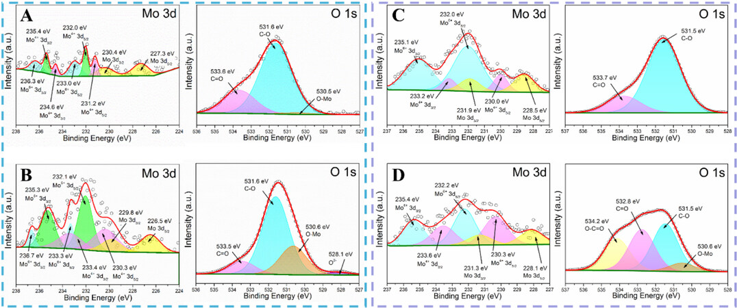
Figure 8. Ex situ X-ray photoelectron spectra measured in a vacuum of Mo and O elements of (A) LMO and (B) LMO@CNF material after being discharged to 0.01 V at a current density of 100 mA g-1. At 3.0 V after one cycle, ex situ X-ray photoelectron spectra of Mo and O elements of (C) LMO and (D) LMO@CNF material.
Comparing the valence states of Mo in Figure 8, it is found that at 3.0 V after one cycle, the peak of Mo6+ becomes stronger, but there is still the existence of low-valence-state Mo, which means that the amorphous Li-Mo-O substance cannot return to the original state of Li2MoO4 after delithiation. This also proves that it is reasonable to recognize the amorphous substances as LixMoyOz or Li-Mo-O. As shown in the X-ray photoelectron spectra of O element in Figure 8D, the O-C=O peak of high oxidation state and the O-Mo peak of low oxidation state are clearly visible. This means that LMO@CNF has a higher oxidation state at 3.0 V, which indicates that with the participation of CNF, it releases more lithium during the delithiation process. This leads to a higher charging capacity for the LMO@CNF, and it also corresponds to a higher initial Coulombic efficiency. The reversible reaction of LixMoyOz ensures that the LMO@CNF can retain a high charge and discharge capacity. The conductive network enables the isolated LMO particles firmly combined with CNF, allowing more LMO to participate in the reaction and contribute to the overall capacity.
To verify the application potential of the anode material, the LMO@CNF anode is coupled with a
CONCLUSIONS
A Li2MoO4@CNF composite material was synthesized via a simple sol-gel method. During cycling, the broken LMO microcrystals can be connected by carbon nanofibers, which enables the composites to show excellent electrochemical performance. The LMO@CNF anode demonstrates a reversible specific capacity of ~830 mAh g-1 at a current density of 100 mA g-1 and still maintains at ~760 mAh g-1 after 100 cycles. A specific capacity of 290 mAh g-1 can still be maintained after 800 cycles at a high current density of 1000 mA g-1, indicating its cycling stability performance. Furthermore, through CV, EIS, in situ and ex situ XRD, XPS, and TEM measurements, the reaction mechanism is explored. The LMO@CNF goes through the discharge process with a first lithiation step turning into Li2+xMoO4, then a phase transition step into Li0.98MoO2, and the Li0.98MoO2 is further converted into Mo and Li2O at low potentials. In the oxidation process, a LixMoyOz amorphous phase is formed, which benefits the electrochemical performance of LMO@CNF regarding high specific capacity and reaction reversibility. This work provides a reliable LMO@CNF anode material with high specific capacity and stability for Li-ion batteries, and attempts are made to reveal the reasons for the excellent performance of the material.
DECLARATIONS
Authors’ contributionsMethodology, formal analysis and writing manuscript: Wang J
Data analysis and technical support: Yao J, Li W
Data acquisition: Zhu W, Yang J
Supervision, writing - review and editing: Zhao J, Gao L
Availability of data and materialsThe data supporting our findings can be found in the supplementary information.
Financial support and sponsorshipSupport from Natural Science foundation of China (U1401248) is acknowledged.
Conflicts of interestAll authors declared that there are no conflicts of interest.
Ethical approval and consent to participateNot applicable.
Consent for publicationNot applicable.
Copyright© The Author(s) 2022.
Supplementary MaterialsREFERENCES
1. Li W, Song B, Manthiram A. High-voltage positive electrode materials for lithium-ion batteries. Chem Soc Rev 2017;46:3006-59.
2. Lu H, Tian K, Bu L, et al. Synergistic effect from coaxially integrated CNTs@MoS2/MoO2 composite enables fast and stable lithium storage. J Energy Chem 2021;55:449-58.
3. Roselin LS, Juang RS, Hsieh CT, et al. Recent advances and perspectives of carbon-based nanostructures as anode materials for Li-ion batteries. Materials 2019;12:1229.
4. Ding B, Cai Z, Ahsan Z, et al. A review of metal silicides for lithium-ion battery anode application. Acta Metall Sin 2021;34:291-308.
5. Lingfei C, Liu Y, Zhang G, Zhang R. Mesoporous MoO2-carbon nanocomposites synthesized by triconstituent co-assembly approach for high performance lithium-ion batteries. Microporous Mesoporous Mater 2021;327:111427.
6. Ding J, Abbas SA, Hanmandlu C, et al. Facile synthesis of carbon/MoO3 nanocomposites as stable battery anodes. J Power Sources 2017;348:270-80.
7. Bai J, Zhao B, Zhou J, et al. Improved electrochemical performance of ultrathin MoS2 nanosheet/Co composites for lithium-ion battery anodes. ChemElectroChem 2019;6:1930-8.
8. Yao J, Liu B, Ozden S, et al. 3D nanostructured molybdenum diselenide/graphene foam as anodes for long-cycle life lithium-ion batteries. Electrochim Acta 2015;176:103-11.
9. Chong S, Sun L, Shu C, et al. Chemical bonding boosts nano-rose-like MoS2 anchored on reduced graphene oxide for superior potassium-ion storage. Nano Energy 2019;63:103868.
10. Chong S, Wei X, Wu Y, et al. Expanded MoSe2 nanosheets vertically bonded on reduced graphene oxide for sodium and potassium-ion storage. ACS Appl Mater Interfaces 2021;13:13158-69.
11. Ju Z, Zhang E, Zhao Y, et al. One-pot hydrothermal synthesis of FeMoO4 nanocubes as an anode material for lithium-ion batteries with excellent electrochemical performance. Small 2015;11:4753-61.
12. Park GD, Hong JH, Lee JK, Kang YC. Yolk-shell-structured microspheres composed of N-doped-carbon-coated NiMoO4 hollow nanospheres as superior performance anode materials for lithium-ion batteries. Nanoscale 2019;11:631-8.
13. Park J, Cho JS, Kang YC. Scalable synthesis of NiMoO4 microspheres with numerous empty nanovoids as an advanced anode material for Li-ion batteries. J Power Sources 2018;379:278-87.
14. Gao L, Chen G, Zhang L, Yan B, Yang X. Engineering pseudocapacitive MnMoO4@C microrods for high energy sodium ion hybrid capacitors. Electrochimica Acta 2021;379:138185.
15. Jiang S, Huang R, Zhu W, et al. Free-Standing SnO2@rGO anode via the anti-solvent-assisted precipitation for superior lithium storage performance. Front Chem 2019;7:878.
16. Zhang J, Lee G, Wing-hei Lau V, et al. Electrochemical grinding-induced metallic assembly exploiting a facile conversion reaction route of metal oxides toward Li ions. Acta Materialia 2021;211:116863.
17. Tan X, Wu Y, Lin X, et al. Application of MOF-derived transition metal oxides and composites as anodes for lithium-ion batteries. Inorg Chem Front 2020;7:4939-55.
18. Bashir T, Ismail SA, Song Y, et al. A review of the energy storage aspects of chemical elements for lithium-ion based batteries. Energy Mater 2021;1:100019.
19. Chen Y, Wang Y, Yang H, et al. Facile synthesis of porous hollow Co3O4 microfibers derived-from metal-organic frameworks as an advanced anode for lithium ion batteries. Ceram Int 2017;43:9945-50.
20. Tian K, Lu H, Bu L, et al. Exploring lithium storage mechanism and cycling stability of Bi2Mo3O12 binary metal oxide anode composited with Ti3C2MXene. Batteries Supercaps 2020;3:1296-305.
21. Wang H, Zou B, Tang Z, Wen Z, Chen C. Enhancing cyclability and rate performance of Li2MoO4 by carbon coating. Mater Lett 2016;177:54-7.
22. Liu X, Zhao Y, Dong Y, et al. Synthesis of one dimensional Li2MoO4 nanostructures and their electrochemical performance as anode materials for lithium-ion batteries. Electrochim Acta 2015;174:315-26.
23. Huang S, Zhou M, Wang K, Cheng S, Yan G, Jiang K. Electrochemical synthesis of Li-Mo-O compounds as novel and high performance anode materials for lithium-ion batteries. J Alloys Compd 2017;712:555-9.
24. Zhang J, Li R, Chen Q, Zhao G, Jia J. Porous carbon-coated Li2MoO4 as high-performance anode materials for lithium-ion batteries. Mater Lett 2018;233:302-5.
25. Liu X, Lyu Y, Zhang Z, et al. Nanotube Li2MoO4: a novel and high-capacity material as a lithium-ion battery anode. Nanoscale 2014;6:13660-7.
26. Barinova O, Kirsanova S, Sadovskiy A, Avetissov I. Properties of Li2MoO4 single crystals grown by Czochralski technique. J Cryst Growth 2014;401:853-6.
27. Bal S. Experimental study of mechanical and electrical properties of carbon nanofiber/epoxy composites. Mater Des (1980-2015) 2010;31:2406-13.
28. Stampfer C, Bürli A, Jungen A, Hierold C. Raman imaging for processing and process monitoring for nanotube devices. phys stat sol 2007;244:4341-5.
29. Han D, Hwang S, Bak S, Nam K. Controlling MoO2 and MoO3 phases in MoOx/CNTs nanocomposites and their application to anode materials for lithium-ion batteries and capacitors. Electrochim Acta 2021;388:138635.
30. Zheng F, Ou X, Pan Q, et al. Nanoscale gadolinium doped ceria (GDC) surface modification of Li-rich layered oxide as a high performance cathode material for lithium ion batteries. Chem Eng J 2018;334:497-507.
31. Zhang X, Liu G, Zhou K, et al. Enhancing cycle life of nickel-rich LiNi0.9Co0.05Mn0.05O2 via a highly fluorinated electrolyte additive - pentafluoropyridine. Energy Mater 2021;1:100005.
32. Hao J, Zhang J, Xia G, et al. Heterostructure manipulation via in situ localized phase transformation for high-rate and highly durable lithium ion storage. ACS Nano 2018;12:10430-8.
33. Zhang H, Wu T, Wang K, et al. Uniform hierarchical MoO2/carbon spheres with high cycling performance for lithium ion batteries. J Mater Chem A 2013;1:12038.
34. Zhang H, Shu J, Wang K, et al. Lithiation mechanism of hierarchical porous MoO2 nanotubes fabricated through one-step carbothermal reduction. J Mater Chem A 2014;2:80-6.
35. Duan L, Li X. Lithiated Mo4O11 to improve excellent cycle stability of MoO2 nanoparticles for lithium-ion battery. Synthetic Metals 2021;272:116672.
36. Maier J. Thermodynamics of electrochemical lithium storage. Angew Chem Int Ed Engl 2013;52:4998-5026.
Cite This Article
Export citation file: BibTeX | RIS
OAE Style
Wang J, Yao J, Li W, Zhu W, Yang J, Zhao J, Gao L. Lithium molybdate composited with carbon nanofibers as a high-capacity and stable anode material for lithium-ion batteries. Energy Mater 2022;2:200026. http://dx.doi.org/10.20517/energymater.2022.22
AMA Style
Wang J, Yao J, Li W, Zhu W, Yang J, Zhao J, Gao L. Lithium molybdate composited with carbon nanofibers as a high-capacity and stable anode material for lithium-ion batteries. Energy Materials. 2022; 2(4): 200026. http://dx.doi.org/10.20517/energymater.2022.22
Chicago/Turabian Style
Wang, Jiaqi, Junyi Yao, Wanying Li, Wenhao Zhu, Jie Yang, Jianqing Zhao, Lijun Gao. 2022. "Lithium molybdate composited with carbon nanofibers as a high-capacity and stable anode material for lithium-ion batteries" Energy Materials. 2, no.4: 200026. http://dx.doi.org/10.20517/energymater.2022.22
ACS Style
Wang, J.; Yao J.; Li W.; Zhu W.; Yang J.; Zhao J.; Gao L. Lithium molybdate composited with carbon nanofibers as a high-capacity and stable anode material for lithium-ion batteries. Energy Mater. 2022, 2, 200026. http://dx.doi.org/10.20517/energymater.2022.22
About This Article
Copyright

Data & Comments
Data


 Cite This Article 17 clicks

 Like This Article 30
likes
Like This Article 30
likes


Comments
Comments must be written in English. Spam, offensive content, impersonation, and private information will not be permitted. If any comment is reported and identified as inappropriate content by OAE staff, the comment will be removed without notice. If you have any queries or need any help, please contact us at support@oaepublish.com.