
Two-dimensional nitrogen and phosphorus co-doped mesoporous carbon-graphene nanosheets anode for high-performance potassium-ion capacitor

Abstract
Heteroatom-doped carbon materials have high gravimetric potassium-ion storage capability because of their abundant active sites and defects. However, their practical applications toward potassium storage are limited by sluggish reaction kinetics and short cycling life owing to the large ionic radius of K+ and undesirable parasitic reactions. Herein, we report a new strategy that allows for bottom-up patterning of thin N/P co-doped carbon layers with a uniform mesoporous structure on two-dimensional graphene sheets. The highly porous architecture and N/P co-doping properties provide abundant active sites for K+, and the graphene sheets promote charge/electron transfer. This synergistic structure enables excellent K+ storage performance in terms of specific capacity (387.6 mAh g-1 at 0.05 A g-1), rate capability (over 5 A g-1), and cycling stability (70% after 3,000 cycles). As a proof of concept, a potassium-ion capacitor assembled using this carbon anode yields a high energy density of 107 Wh kg-1, a maximum power density of 18.3 kW kg-1, and ultra-long cycling stability over 40,000 cycles.
Keywords
INTRODUCTION
With the prosperous development and commercialization of electric vehicles and grid-scale energy storage, electrochemical energy storage systems with high energy and power densities as well as long-term cycling stability have been urgently necessitated[1]. Lithium-ion capacitors (LICs) consisting of a Faradaic redox anode and a capacitive cathode offer high energy and power densities as well as long-term cycle life, thus leading to solid technological support for novel electric and electronic applications[2,3]. Nevertheless, the soaring price of Li resources renders LICs economically unfavorable, thus necessitating the development of low-cost alternative energy-storage devices[4]. Among them, potassium-ion capacitors (PICs) have emerged as promising candidates because of the abundant K resources (2.09 wt.% of the earth’s crust, more than 1,000 times the abundance of Li) and similar working mechanism to LICs[5-7]. In addition, the redox potential of K+/K (-2.93 V vs. SHE) is very close to that of Li/Li+ (-3.04 V vs. SHE), suggesting the highly comparable working potentials of PICs to LICs, as well as the decent energy density[8]. However, the large ionic radius of K+ (1.38 Å) gives rise to a large volume change and sluggish redox reaction for most anodes during potassiation/depotassiation, resulting in poor rate capability and short cycle life[9,10]. These disadvantages further broaden the kinetic gap between the anode and cathode, which is a major issue in the development of PICs. Hence, it is highly desirable to exploit novel anode materials with low cost and high electrochemical performance for PICs with high commercial potential.
Among the various anode materials, carbonaceous materials are considered promising candidates for anodes because of their high electrical conductivity, physicochemical stability, low cost, and environmental friendliness[9,11,12]. The mechanism of K+ storage in carbonaceous materials primarily arises from the reversible in-/de-tercalation of K+ into carbon layers[11,13]. However, the intercalation process of K+ is kinetically limited, which usually leads to low-rate performance. Additionally, the final product of the K+ intercalated product (KC8) displays only a mediocre theoretical specific capacity of 279 mAh g-1[11]. To overcome the inherent weakness of carbon anodes, two intuitive and commonly used approaches have been reported to create nano or porous structures as well as heteroatom doping (e.g., N, P, O, S, F, B, etc.)[14-21]. The major function of the nano- or porous structure is to minimize K+ solid-state diffusion distances, thus enabling more rapid K+ transport throughout the electrode and increasing the surface area of electrode material in contact with electrolyte[9,10]. Currently, carbon materials with various nano- or porous structures, including carbon nano-crumples[16], porous carbon spheres[17], accordion-like carbon[18], carbon nanoboxes[19], carbon nanoballs[20], carbon nanofibers[21], have proven to be more beneficial for K+ intercalation and exhibit much-improved performance, especially in rate capability. Heteroatom doping tends to create abundant active sites and defects, thereby enhancing the adsorption of K+[22]. The doping effect for enhancing the K+ storage largely depends on the functions endowed by the doping elements in general[9]. As for N doping, pyridine-N and pyrrole-N help improve K+ adsorption activity, while graphitic-N can enhance the rate capability[23]. It was reported that P doping could improve the structural stability and form P-C and P-O/P-OH bonds, thus contributing to the rapid surface-controlled behavior of K adsorption[17]. More evidence has shown that O doping could reduce the inert surface area to improve the wettability and offer abundant active sites to enhance the capacity. However, O doping can reduce electrical conductivity, resulting in a short cycling life[24]. Recent studies have shown that F doping leads to the formation of favorable F-C bonding sites and the creation of edge defects owing to the large electronegativity, thus facilitating fast K+ transfer[25]. S-doping usually provides active sites for K+ adsorption and desorption. In addition, S-doping catalyzes and accelerates the reduction and decomposition of the electrolyte to form a thick solid electrolyte interface (SEI) through the formation of C-S-C bonds[26]. Density functional theory (DFT) calculations showed that B-doping tends to convert carbon into p-type semiconductors and significantly decreases the cell voltage, possibly reducing the performance of K+ storage[27]. Multiple-element doping (e.g., P/O[17], B/N[16,20], N/F[21], N/O[24], etc.) has recently been demonstrated as an effective strategy to solve the issues caused by single heteroatom doping, further improving the K+ storage performance. Therefore, well-designed carbonaceous materials with controllable porous structures and optimal heteroatom dopants can enhance the overall level of K+ storage, thereby boosting the energy and power densities of PICs.
Herein, we report the hard-template synthesis of thin N/P co-doped carbon layers with mesoporous structure uniformly grown on freestanding graphene sheets to generate a new 2D carbon material (denoted as N/P-MC@RGO). By using the synergistic effects arising from the highly porous architecture and N/P co-doping properties of carbon coatings, as well as a highly conductive graphene substrate, the N/P-MC@RGO anode showed impressive K+ storage properties, including enhanced specific capacity, high rate capability, and robust cycling stability. As a result, a novel PIC fabricated by using N/P-MC@RGO as the negative electrode and homemade activated porous carbon as the positive electrode, shows a large working voltage of 4.2 V, a maximum energy density of 107 Wh kg-1 and a maximum power density of 18,300 W kg-1. Furthermore, an ultra-long cycling life of over 40,000 cycles with a 76.3% capacity retention was recorded for this PIC.
EXPERIMENTAL
Materials synthesis
Ludox HS-40 silica colloid solution (40 wt.%) with an average size of ~12 nm was purchased from Sigma Aldrich. Aniline (GC, > 99.9%), ammonium persulfate (AR, > 98%), phytic acid solution (AR, 70%), hydrofluoric acid (AR, 40%), potassium chloride (AR), hydrochloric acid (AR, 37%), and Poly(diallyldimethylammonium chloride) solution (PDDA, 20 wt.% in water) were purchased from Aladdin chemicals. All the chemicals were used directly without further purification.
Graphene oxide (GO) was synthesized by a modified Hummers’ method. KCl (50 mg) and PDDA (150 mg) were mixed and then stirred with GO solution (25 mL, 1 mg mL-1) for 6 h. After that, the supernatant was removed after centrifugation to obtain the functionalized GO with positive charge. The positively charged GO was re-dispersed into 250 mL water to form a mixture, followed by ultrasonication for more than
Materials characterization
Field emission scanning electron microscopy (FESEM, SU-70, Hitachi, Japan) was employed to study the morphologies of the samples. Powder X-ray diffraction (XRD, D/Max-2400, Rigaku, Tokyo, Japan) using Cu-Kα radiation and transmission electron microscopy (TEM, Tecnai F20, FEI Company, USA) were employed to obtain the structural information of the samples. Raman spectral analysis was performed on a JY-HR800 micro-Raman spectroscope with an excitation wavelength of 532 nm. The surface morphologies and thicknesses of samples were recorded by atomic force microscopy (AFM, Bruker, MultiMode 8). The surface chemical species of as-prepared samples were recorded by an X-ray photoelectron spectroscopy (XPS, Perkin-Elmer PHI-5702 Spectrometer, USA). An ASAP 2020 volumetric adsorption analyzer (Micromeritics, USA) was used to probe the pore structures of as-prepared samples at 77 K.
Electrodes preparation
To achieve the N/P-MC@RGO anode, 80 wt.% of N/P-MC@RGO, 10 wt.% of conducting filler-acetylene black, and 10 wt.% of binder-polyvinylidene fluoride (PVDF) dissolved into methy l-2-pyrrolidone (NMP) were mixed in a mortar. The resulting slurry was then homogeneously coated on the Cu foil homogeneously by a scraper, which was further dried at 110 °C under vacuum. Note that the active mass loading on Cu foil was 0.5-0.8 mg. A 2,032 type coin cell was used for the fabrication of PICs, where N/P-MC@RGO was used as the anode; K metal foil was used as the reference and counter electrode; a round glass-fiber membrane (Whatman, USA) was used as the separator. A 2,032 type coin cell was used for the fabrication of PICs, where the pre-potassiated N/P-MC@RGO was used as the negative electrode; a homemade polyaniline derived porous carbon (PDPC) was used as the positive electrode, and a round glass-fiber membrane (Whatman, USA) was used as the separator. Before the fabrication of PICs, N/P-MC@RGO electrode was pre-cycled for 3-5 cycles under a current density of 0.05 A g-1 and ended in a potassiated state at 0.01 V in a half cell. The half cell was placed in a glovebox under an Ar filled atmosphere and then detached to achieve the pre-potassiated N/P-MC@RGO electrode. 1 M KPF6 in EC:DMC:EMC = 1:1:1 vol.% was employed as the electrolyte for half and full cells. For all the cells, only ~80 μL of electrolyte was added. To assemble the half/full cells, Ar filled glovebox with the low O2 and H2O contents (less than 0.1 ppm) was employed.
RESULTS AND DISCUSSION
Two-dimensional N/P-MC@RGO was prepared through a facile template method, as depicted in Figure 1A. As shown in the scanning electron microscopy (SEM) images of Figure 1B and C, the resulting N/P-MC@RGO nanosheets preserve the lamellar structure and highly curly morphology of RGO substrate
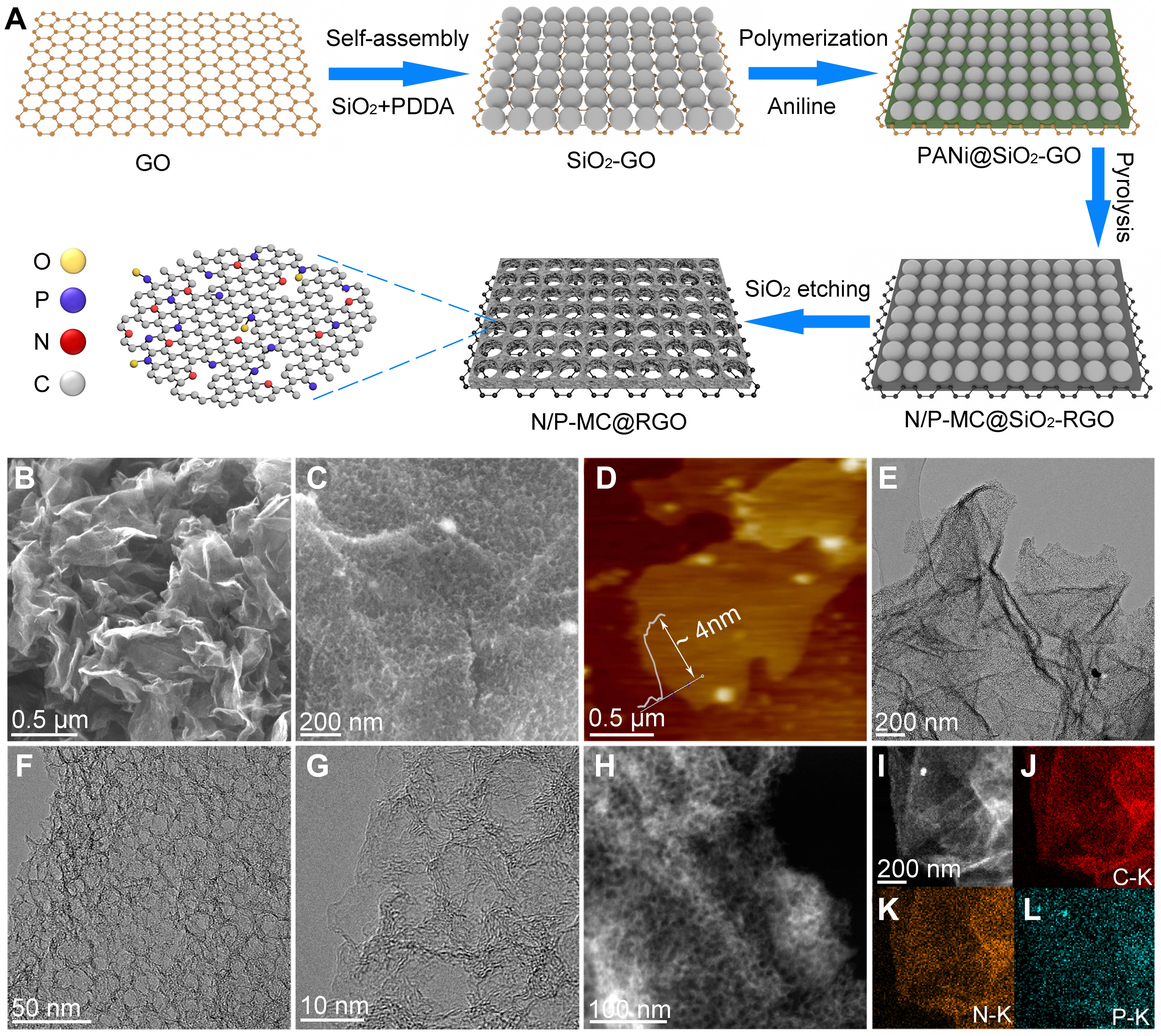
Figure 1. (A) Typical synthetic procedures of N/P-MC@RGO sample. Characterization of 2D N/P-MC@RGO: (B and C) SEM images, (D) AFM image, (E-G) TEM images of N/P-MC@RGO, (H and I) ADF-STEM image and the corresponding EDS mapping of (J) C, (K) N, and (L) P.
Figure 2A displays the X-ray diffraction (XRD) patterns of the as-prepared RGO, N/P-MC, and N/P-MC@RGO samples. All these XRD patterns show a predominantly broad peak centered at around 24°, which corresponds to the (002) reflection of graphite. The broad peak profile of these samples suggests a low degree of graphitization and a highly defective property. Additionally, the average graphene domain heights (Lc) for N/P-MC@RGO were further evaluated using Scherrer equation[28,29]. The Lc value was estimated to be 0.948 nm, which suggests that the carbon nanosheets are composed of 2-3 layer-stacked graphene sheets (e.g., 0.948 nm/0.34 nm = ~2.78) surrounded by disordered regions, which is highly consistent with TEM observation. The few-layered stacked graphene structure is also observed in the RGO (Lc = 0.88 nm) and N/P-MC (Lc = 1.15 nm) samples.
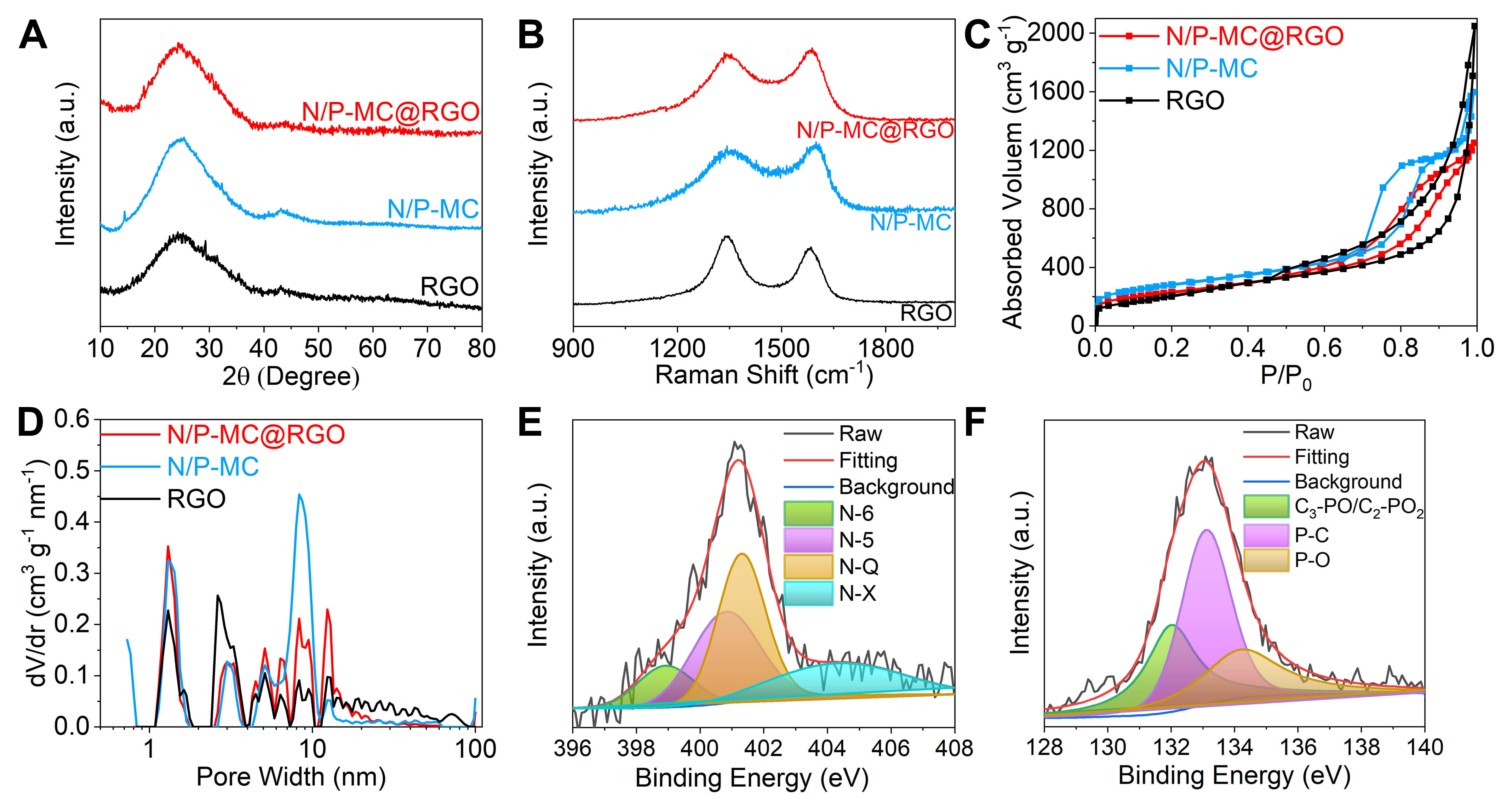
Figure 2. Structural characterizations of N/P-MC@RGO, N/P-MC and RGO samples: (A) XRD, (B) Raman, (C) nitrogen adsorbed/desorbed isotherms, (D) pore-size distribution. XPS spectra of N/P-MC@RGO including high-resolution (E) N 1s and
Raman spectroscopic analysis was employed to further investigate the structure of as-prepared carbon samples, as shown in Figure 2B. Two broad peaks around 1,350 cm-1 and 1,590 cm-1 are observed, corresponding to disorder-induced D-band and in-plane vibrational G-band (1,590 cm-1), respectively. We then evaluated the degree of graphitic ordering for these samples according to the areal intensity value ratio between the D- and G-bands (ID/IG)[30,31]. For N/P-MC@RGO, ID/IG value is calculated to 1.34, which is slightly higher than RGO with ID/IG value of 1.23 and lower than N/P-MC, with ID/IG value of 1.76
Brunauer-Emmet-Teller (BET) characterization was employed to investigate the pore structure of as-prepared carbon samples. Figure 2C shows the N2 adsorption/desorption isotherms of N/P-MC@RGO and N/P-MC with a type H4 hysteresis at the high-pressure region, suggesting the presence of abundant accessible mesopores after the introduction of a colloidal SiO2 template. For comparison, an isotherm of RGO has a type H3 loop, which is indicative of slit-like pores formed by a loose assembly of graphene sheets. The pore-size distribution curve of N/P-MC@RGO sample [Figure 2D] further confirmed the presence of narrow micropores centered around 1.2 nm and broad mesopores with sizes ranging from
X-ray photoelectron spectroscopy (XPS) analysis was further employed to probe the surface element components and chemical state of as-prepared carbon samples. The full XPS spectrum of N/P-MC@RGO clearly shows the peaks of C, N, O and P [Figure 2E and Supplementary Figure 4]. The contents of N, P and O heteroatoms were evaluated to be 3.55, 1.80 and 9.94 at%, respectively [Supplementary Table 1]. The contents of N and P heteroatoms of N/P-MC@RGO are slightly higher than that of N/P-MC. For comparison, RGO sample is mainly composed of C and O atoms with less N and P contents
The K+ storage properties were evaluated by half-cells in which potassium metal was used as counter electrode and KPF6 based organic solution was used as electrolyte. Supplementary Figure 6 shows the CV curve of the N/P-MC@RGO electrode at 0.2 mV s-1 within a potential window between 0.01 and 3.00 V (vs. K+/K). In the initial potassium cycle, an obvious cathodic peak near 0.51 V (vs. K+/K) arises and then reduces in the subsequent cycles, which can be assigned to the formation of solid electrolyte interphase (SEI) film caused by irreversible parasitic reactions between surface functional groups and electrolyte[23,24,32]. When the potential drops below 0.40 V (vs. K+/K), the current density of cathodic peak increases rapidly, which is mainly related to the synergistic effect of K+ insertion into the layers of N/P-MC@RGO and the irreversible side effects between electrolyte with surface functional groups[23,24,32]. During the following anodic process, the CV curve is roughly horizontal without an obvious anodic peak, suggesting the multiple charge storage mechanisms caused by the gradual extraction of K+ from the graphene layers and the reversible surface redox reaction between K+ and heteroatom functional groups[32,36]. In contrast, the following CV curves tend to overlap, which indicates that the potassiation/depotassiation process that occurred on N/P-MC@RGO is highly reversible.
Figure 3A shows the initial galvanostatic charge/discharge curves of N/P-MC@RGO at a rate of 0.05 A g-1. The initial discharge capacity is over 2,952 mAh g-1, but the initial reversible charging capacity is only
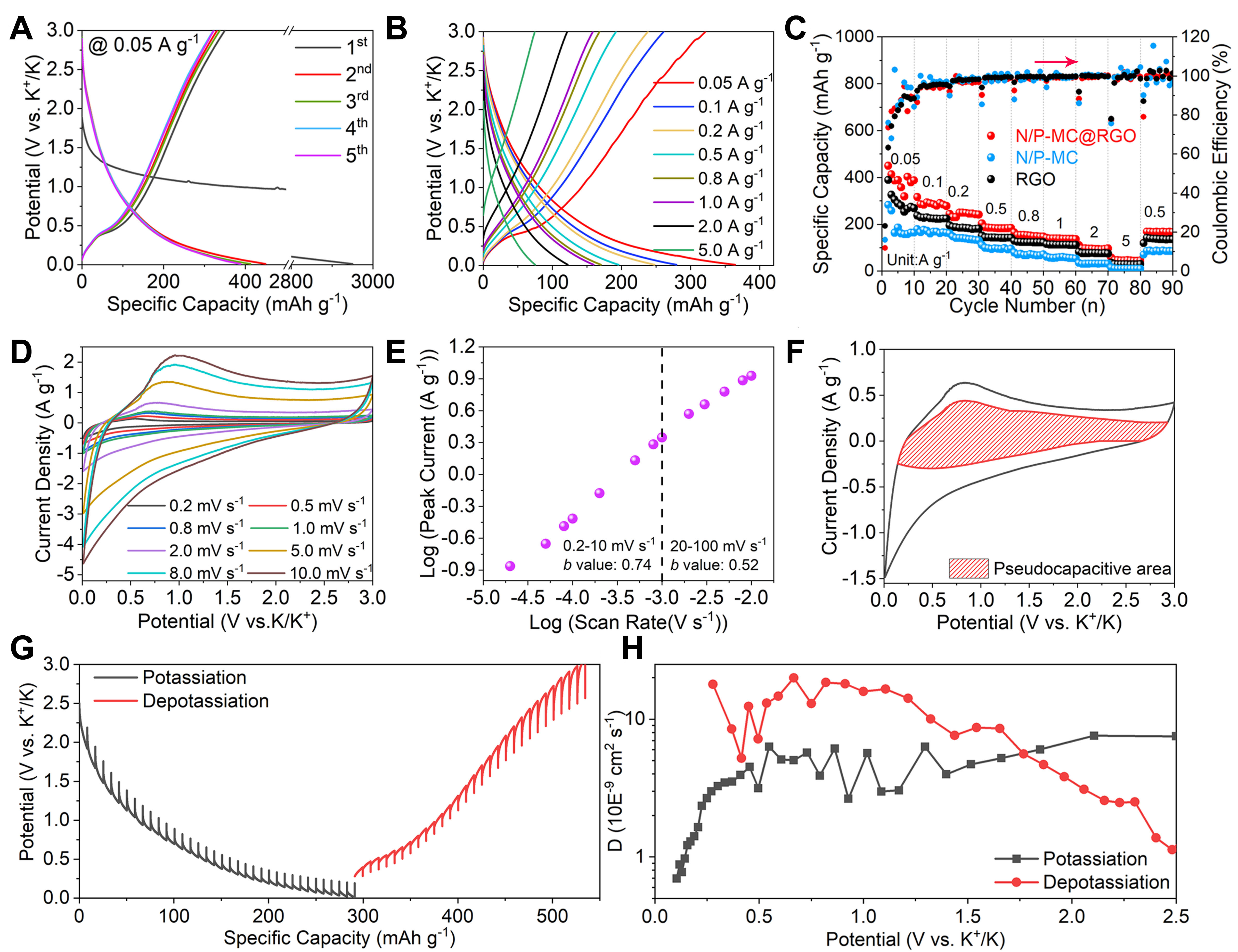
Figure 3. K+ storage behaviour of N/P-MC@RGO anode in half cells. (A) Initial charge/discharge curves at a rate of 0.05 A g-1. (B) Galvanostatic charging/discharging curves at different rates. (C) Rate capability achieved from 0.05-5.00 A g-1. (D) CV patterns ranging from 0.2-10 mV s-1. (E) b-value evaluated from the anodic peak currents. (F) Voltammetry response for N/P-MC@RGO electrode at 5 mV s-1. The shaded region is related to the capacitive contribution to the total current. (G) GITT test on N/P-MC@RGO anode. (H) The K+ diffusion coefficient evaluated by GITT method during the different charge/discharge processes.
Figure 3B shows that all the charge-discharge curves (from 0.05-5 A g-1) of N/P-MC@RGO show a triangular profile without voltage plateaus, which is identical to that of other porous carbons[19,32,35] and heteroatoms doping carbon anodes[27,34-36]. Noted that the triangular profile for N/P-MC@RGO is totally different from battery-type anodes which have obvious charge/discharge plateaus, for example, Bi[40] and P[41]. This slope characteristic of charge/discharge curves is mainly related to the highly porous structure and heteroatoms doping characteristic of N/P-MC@RGO, which provide abundant active sites for K+ storage with fast behaviour. We then evaluated the rate performance of N/P-MC@RGO electrodes at different rates ranging from 0.05 to 5 A g-1. Figure 3C shows that the reversible capacities of N/P-MC@RGO are 387.6, 277.9, 241.5, 184.2, 147.5, 136.4, 96.6 and 44.9 mAh g-1, corresponding to the rates of 0.05, 0.1, 0.2, 0.5, 0.8, 1, 2 and 5 A g-1, respectively. In contrast, RGO and N/P-MC anodes show lower specific capacities and inferior rate performance. The enhanced K+ charge-storage performance of N/P-MC@RGO is mainly related to the enhanced conductivity caused by the RGO introduction and more accessible active sites provided by two-dimensional sheet-like morphology. For all these carbon anodes, the CE values gradually increase and approach ~100% as the charge/discharge current density is over 0.5 A g-1, indicating the stable SEI layer achieved after several repeating charging/discharging processes.
CV measurements were further employed to study the reaction kinetics of K+ charge storage of N/P-MC@RGO. Figure 3D and Supplementary Figure 7 display the CV curves at the different sweep rates ranging from 0.2-100 mV s-1. All the CV curves show a similar profile with broad anodic peaks and indistinct cathodic peaks, suggesting a possible pseudocapacitive behaviour during the potassiation/depotasiation process. A power law was employed to study the relationship between the peak current (i) and scanning rate (v)[42-44]:
where a and b are the appreciated values. Previous studies pointed out that a b-value of 0.5 suggests a diffusion-controlled behaviour related to ion diffusion into the bulk, whereas a b-value of 1 suggests a capacitive behaviour through a surface Faradaic redox process[42,43]. The slope of the log(v)-log(i) plots can be used to determine the b-value. As shown in Figure 3E, at sweep rates from 0.2 to 10 mV s-1, the b-value is quantified to 0.74 for cathodic peaks, which suggests that the charge storage of N/P-MC@RGO arises from surface-controlled behaviour. For sweep rates above 10 mV s-1, the b-value decreases to 0.52, which is related to the Ohmic contribution or diffusion limitation[42,43]. The capacitive contribution was further qualified according to the approach proposed by Dunn et al.[43]. As shown in Figure 3F, at a sweep rate of
To provide a deep understanding of K+ diffusion kinetics of N/P-MC@RGO, galvanostatic intermittent titration technique (GITT) was performed. Figure 3G depicts the potential response of N/P-MC@RGO anode during the GITT test at 0.1 A g-1, which makes no difference to the above-mentioned galvanostatic charge/discharge curves. The Dk values were determined by solving Fick’s second law
In addition to the high K+ charge storage capacity, N/P-MC@RGO electrode also exhibits excellent cycling stability. Supplementary Figure 15 shows that N/P-MC@RGO anode preserves ~81.7% of initial capacity after 600 charge/discharge cycles at a rate of 0.2 A g-1. Even after the long-term 3,000 charge/discharge cycles at a rate of 0.5 A g-1, the specific capacity still maintains ~70% of the initial capacity [Figure 4A]. The coulombic efficiency values are close to 100% during the whole cycling process. Electrochemical impedance spectroscopy (EIS) analysis shown in Figure 4B and Supplementary Figure 14 suggests that the capacity decay of N/P-MC@RGO anode is mainly associated with the increase in SEI resistance and the step-down K+ diffusion after the long cycles[47].
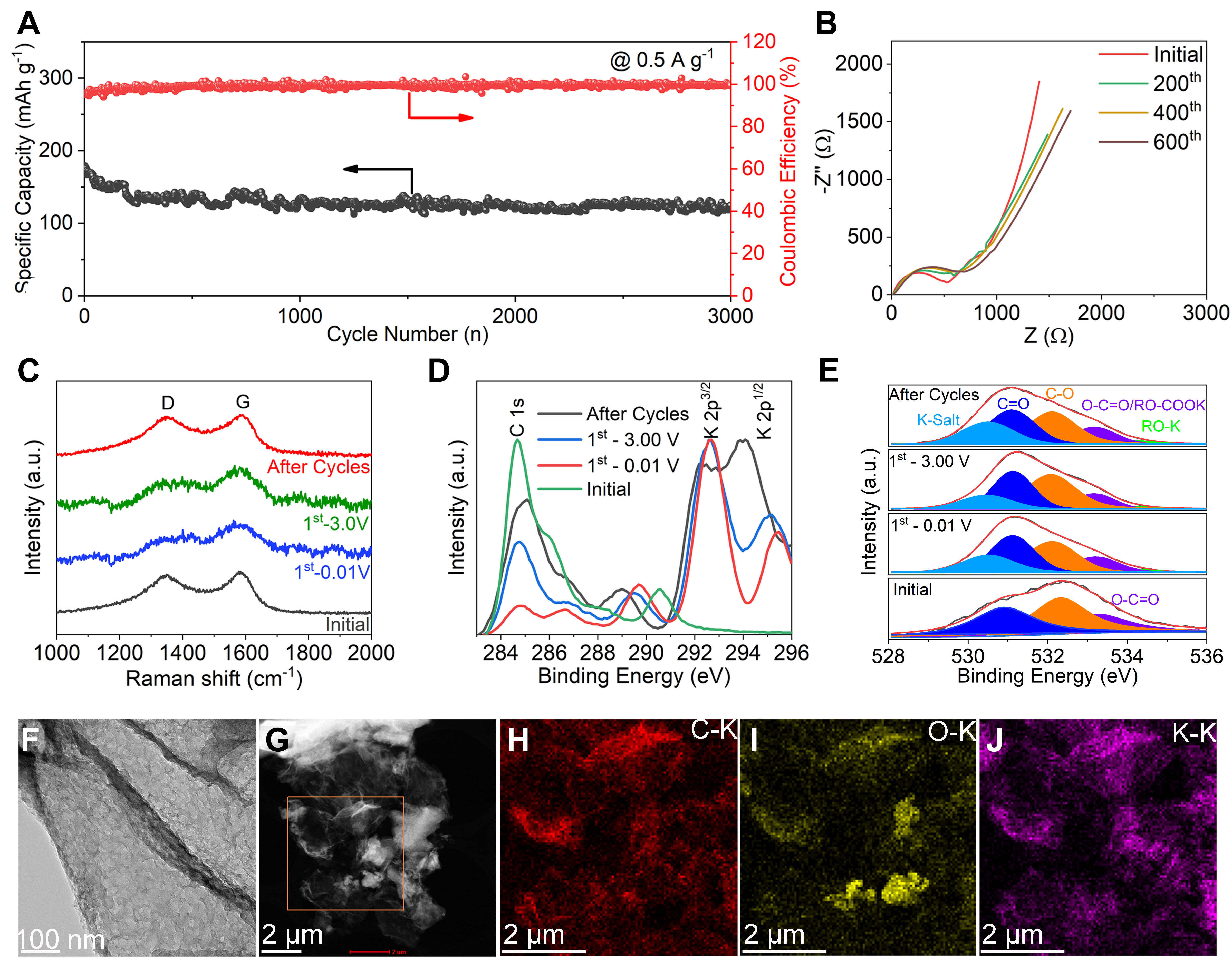
Figure 4. Electrochemical performance, structural evolution, and surface information of N/P-MC@RGO anode during the K+ storage. (A) Cycling performance at a rate of 0.5 A g-1. (B) EIS spectra achieved after different cycles under a constant charging/discharging rate of 0.2 A g-1. (C) Ex situ Raman spectra, (D) C1s and K2p, (E) O1s XPS spectra for N/P-MC@RGO during the different charging/discharging stages. (F) TEM image, (G) ADF-STEM image, and the corresponding EDS mapping of (H) C-K, (I) O-K, and (J) K-K for N/P-MC@RGO after the long-term cycles.
In addition, ex-situ Raman, XPS, and TEM measurements were performed on N/P-MC@RGO anode to study its good electrochemical properties during the potassiated and depotassiated processes. The ex-situ Raman analysis in Figure 4C shows that D and G peaks of N/P-MC@RGO broadened after the K+ insertion, which may be related to the interference between the metal-like behaviour of KCx intercalated compounds and the resonant phonon scattering process[48,49]. D and G peaks of N/P-MC@RGO have still preserved after the potassiated and depotassiated process as well as the long cycles (600 cycles at 0.2 A g-1), suggesting the highly reversible process and structural stability of N/P-MC@RGO anode.
Supplementary Figure 16 shows the full spectrum of ex-situ XPS at the different charging and discharging states during initial and long-term cycles. We noted that the intensity of C1s peak around 284.8 eV was largely reduced during the initial potassiation process [Figure 4D], whereas several new peaks appeared in high binding energy area ranging from 286-296 eV, which is closely related to SEI formation or KCx intercalated compounds. Specifically, two prominent XPS peaks around 286.5 eV and 289.6 eV can be assigned to C-O and O-C=O/RO-ROOK/KHCO3 [Supplementary Figure 17A], respectively, mainly stemming from SEI formation caused by the decomposition of electrolyte[32,50]. The existence of K-salt, RO-COOK and RO-K was further demonstrated by high-resolution O1s spectrum [Figure 4E]. In addition, two strong K2p peaks around 293.0 eV and 295.5 eV could be observed in Figure 4D, suggesting the formation of SEI and K+ inserted into carbon matrix. We also noted that after the depotassiation, the intensity of C1s peak slightly increased, suggesting the reversibility of K+ insertion and desertion process. The pristine N1s XPS peaks are almost disappeared after potassiation [Supplementary Figure 17B], and the pristine P2p XPS peak shifted to a high binding energy around 137.8 eV which is indicative of P-F species
SEM was employed to characterize the surface morphologies of N/P-MC@RGO anode before and after the cycling. Supplementary Figure 18 displays that SEI was uniformly coated on the N/P-MC@RGO electrode after the long cycles, providing viable evidence for long-term cycling stability. TEM was further performed to investigate the structural characteristics of N/P-MC@RGO after the long cycles. N/P-MC@RGO still maintains the pristine 2D layer structure after the long-term cycling, as indicated by TEM images [Figure 4F and Supplementary Figure 19] and the ADF-STEM image [Figure 4G]. Meanwhile, thin SEI was uniformly coated on N/P-MC@RGO electrode, which was further confirmed by EDS mappings in which K, O, F, and P elements were distributed homogeneously throughout the carbon matrix [Figure 4H-J and
To further uncover the relationship between N and P co-doping structure and the enhanced K+ charge storage properties of N/P-MC@RGO, density functional theory (DFT) calculations were employed. Seven regularly repeated carbon laboratory models were established for systematic study, namely G-C (pure graphene or graphite, Figure 5A), N5-C (pyridine nitrogen-doped carbon, Figure 5B), N5/P-C (pyridine nitrogen and phosphorus-doped carbon, Figure 5C), N6-C (pyridine nitrogen-doped carbon, Figure 5D), N6/P-C (pyrrole nitrogen and phosphorus-doped carbon, Figure 5E), NQ-C (graphite-nitrogen-phosphorus doped carbon, Figure 5F), NQ/P-C (graphite-nitrogen-phosphorus doped carbon, Figure 5G). In these models, graphene was used to represent the structure of a carbon system. As K+ is absorbed in these systems, the most stable electron structure can be confirmed. Additionally, the adsorption energy (ΔEad) can be evaluated by the following equation:

Figure 5. Seven calculation models after K+ absorption on (A) G-C, (B) N5-C, (C) N5/P-C, (D) N6-C, (E) N6/P-C, (F) NQ-C (graphite-nitrogen doped carbon) and (G) NQ/P-C. (H-N) Charge density difference of various models. (The isosurfaces level = 0.0015 e Bohr-3. The cyan areas represent charge depletion; the yellow areas represent charge accumulation, and the brown, red, blue, and green balls represent C, N, P, and K atoms, respectively).
Where the Esub represents the total energy of an isolated carbon system; EK represents the total energy of K atoms; EK+sub represents the total energy of the system with K adsorbed on the carbon substrate.
The calculated ΔEad values are summarized in Supplementary Table 3. From XPS analysis in Figure 2E, N-Q and N5 are the main nitrogen doping forms in N/P-MC@RGO, the corresponding ∆Ead values of N5 and NQ are -2.96 and -0.89 eV, respectively. After extra P doping, the ΔEad values of N5/P-C and NQ/P-C increase up to -3.03 eV and -1.61 eV, respectively. Hence, N, P co-doped structures possess a stronger adsorption ability to K+ compared to single-N or -P doping structure, which is a rational explanation for the enhanced K+ charge storage properties of N/P-MC@RGO. In fact, a reverse trend on ΔEad between N6 and N6/P is observed, but N6 accounts for a limited proportion of N-doping structure for N/P-MC@RGO. Therefore, selective N doping plays an important role in improving the K storage performance of carbon materials. Differential charge density was evaluated to probe the bonding conditions of K adsorbed on various N and/or P heteroatoms in graphene [Figure 5H-N]. The charge transfer between K atoms and various N/P doped graphene substrates can be observed in all models, suggesting the charge transfer from the adsorbed K to the nearest adjacent carbon atom. Noted that the charge accumulation in N5/P-C and NQ/P-C is more obvious than in N5 and NQ, which indicates N/P co-doping has a stronger adsorption capacity to K+ than individual N or P doping, thus being conducive to the capacitance performance. Overall, the above structural, electrochemical, and theoretical analysis clearly demonstrates that the unique 2D layered, ordered mesoporous, and N/P co-doping structure of N/P-MC@RGO accounts for the excellent K+ charge storage properties including large specific capacity, high rate, and excellent cycling stability. Such structural and electrochemical merits enable N/P-MC@RGO to be a promising candidate for PICs with exceptional electrochemical performance.
A PIC was then assembled with N/P-MC@RGO and homemade PDPC as the negative and positive electrodes, respectively, in a 1M KPF6 organic electrolyte, as schematically illustrated in Figure 6A. More information on PDPC electrodes can be seen in our previous work[51]. According to the electrochemical performance of as-fabricated PICs with the different negative/positive mass ratios shown in

Figure 6. Electrochemical performance of N/P-MC@RGO//PDPC PIC. (A) Schematic image of the assembled N/P-MC@RGO//PDPC PIC. (B) CVs achieved under the varied scan rates. (C) Charge/discharging curves under the elevated rates. (D) Rate performance. (E) Ragone plots from our PIC and other reported PICs. (F) Cycling performance at 2 A g-1
Figure 6E shows the Ragone plot (energy density vs. power density) of as-assembled N/P-MC@RGO//PDPC PIC. This PIC delivers a high energy density of 107.0 Wh kg-1 at a power density of 436.8 W kg-1. Even at the ultrahigh power density of 18.3 kW kg-1, N/P-MC@RGO//PDPC PIC can still provide an energy density of 25.4 Wh kg-1. Additionally, the power and energy densities of N/P-MC@RGO//PDPC PIC are highly comparable to those of many the state-of-art reported PICs based carbon anodes including soft carbon (SC)//AC[52], nitrogen-doped graphene (N-Graphene)//AC[53], Graphite//AC[54], nitrogen-doped hollow carbon spheres (NHCS)//ANHCS[55], nitrogen/phosphorus co-doped graphene (N/P-Graphene)//AC[56], N-doped carbon nanotubes (NCNTs)//AC[57], hard carbon (HC)//AC[58], nitrogen-doped carbon nanotubes (N-CNTs)//LSG[59], Mn-MOF derived porous carbon (MDPC)//PDPC[32]
CONCLUSIONS
In summary, we have demonstrated a robust and versatile strategy for bottom-up patterning of N/P co-doped carbon with partially ordered mesopores and large interlayer spacing on 2D graphene. Such rationally designed architecture of N/P-MC@RGO increased the atomic interface contact with K+, thus shortening the ion diffusion path and facilitating charge transfer. Half-cell test combined with other ex-situ structure characterizations confirmed that robust and reversible potassiated/depotassiated processes occurred on N/P-MC@RGO anode. A PIC was fabricated using N/P-MC@RGO as the negative electrode and PDPC as the positive electrode, yielding a high working potential of 4.2 V, a maximum energy density of 107 Wh kg-1 and a maximum power density of 18.3 kW kg-1. Furthermore, this PIC was capable of working for more than 40,000 cycles, showing an excellent cycling performance. Therefore, our work introduces an avenue for the controlled synthesis of 2D carbon materials with well-defined mesoporous architectures and highly heteroatom doping properties toward low-cost, high-performance K-ion based electrochemical devices, such as capacitors and batteries.
DECLARATIONS
Authors’ contributionsMethodology, formal analysis and writing manuscript: Li T, Huang X, Lei S, Li X, Zhang J, Wang S, Wang R
Data analysis and technical support: Li T, Huang X, Lei S, Li X, Wang C, Zhang Z, Yin L
Data acquisition: Li T, Huang X, Lei S, Li X
Supervision, writing - review and editing: Li T, Huang X, Lei S, Zhang J, Wang S, Wang R
Availability of data and materialsNot applicable.
Financial support and sponsorshipThis work was supported by the National Natural Science Foundation of China (51902188, 52272224), Natural Science Foundation of Shandong Province (ZR2021ME124), Innovation Capacity Improvement Project of Small and Medium-Sized Technology-Based Enterprise of Shandong Province (2021TSGC1149), and Youth Innovation Team Project of Shandong Provincial Education Department (10000082295015).
Conflicts of interestAll authors declared that there are no conflicts of interest.
Ethical approval and consent to participateNot applicable.
Consent for publicationNot applicable.
Copyright© The Author(s) 2023.
Supplementary MaterialsREFERENCES
1. Jain R, Lakhnot AS, Bhimani K, et al. Nanostructuring versus microstructuring in battery electrodes. Nat Rev Mater 2022;7:736-46.
2. Ding J, Hu W, Paek E, Mitlin D. Review of hybrid ion capacitors: from aqueous to lithium to sodium. Chem Rev 2018;118:6457-98.
3. Xing F, Bi Z, Su F, Liu F, Wu Z. Unraveling the design principles of battery-supercapacitor hybrid devices: from fundamental mechanisms to microstructure engineering and challenging perspectives. Adv Energy Mater 2022;12:2200594.
4. Li M, Lu J, Ji X, et al. Design strategies for nonaqueous multivalent-ion and monovalent-ion battery anodes. Nat Rev Mater 2020;5:276-94.
5. Wu Y, Sun Y, Tong Y, et al. Recent advances in potassium-ion hybrid capacitors: electrode materials, storage mechanisms and performance evaluation. Energy Stor Mater 2021;41:108-32.
6. Li T, Zhao H, Li C, Yu W, Shi Y, Wang R. Recent progress and prospects in anode materials for potassium-ion capacitors. New Carbon Mater 2021;36:253-77.
7. Arnaiz M, Shanmukaraj D, Carriazo D, et al. A transversal low-cost pre-metallation strategy enabling ultrafast and stable metal ion capacitor technologies. Energy Environ Sci 2020;13:2441-9.
8. Zhang T, Mao Z, Shi X, et al. Tissue-derived carbon microbelt paper: a high-initial-coulombic-efficiency and low-discharge-platform K+-storage anode for 4.5 V hybrid capacitors. Energy Environ Sci 2022;15:158-68.
9. Zhang W, Liu Y, Guo Z. Approaching high-performance potassium-ion batteries via advanced design strategies and engineering. Sci Adv 2019;5:eaav7412.
10. Hosaka T, Kubota K, Hameed AS, Komaba S. Research development on K-ion batteries. Chem Rev 2020;120:6358-466.
11. Li Y, Lu Y, Adelhelm P, Titirici MM, Hu YS. Intercalation chemistry of graphite: alkali metal ions and beyond. Chem Soc Rev 2019;48:4655-87.
12. Yang J, Zhai Y, Zhang X, et al. Perspective on carbon anode materials for K+ storage: balancing the intercalation-controlled and surface-driven behavior. Adv Energy Mater 2021;11:2100856.
13. Alvin S, Cahyadi HS, Hwang J, Chang W, Kwak SK, Kim J. Revealing the intercalation mechanisms of lithium, sodium, and potassium in hard carbon. Adv Energy Mater 2020;10:2000283.
14. Chen J, Yang B, Liu B, Lang J, Yan X. Recent advances in anode materials for sodium - and potassium-ion hybrid capacitors. Curr Opin Electrochem 2019;18:1-8.
15. Cai P, Momen R, Tian Y, et al. Advanced pre-diagnosis method of biomass intermediates toward high energy dual-carbon potassium-ion capacitor. Adv Energy Mater 2022;12:2103221.
16. Lian X, Zhou J, You Y, et al. Boosting K+ capacitive storage in dual-doped carbon crumples with B-N moiety via a general protic-salt synthetic strategy. Adv Funct Mater 2022;32:2109969.
17. Zhao S, Yan K, Liang J, et al. Phosphorus and oxygen dual-doped porous carbon spheres with enhanced reaction kinetics as anode materials for high-performance potassium-ion hybrid capacitors. Adv Funct Mater 2021;31:2102060.
18. Zhang C, Liu X, Li Z, et al. Nitrogen-doped accordion-like soft carbon anodes with exposed hierarchical pores for advanced potassium-ion hybrid capacitors. Adv Funct Mater 2021;31:2101470.
19. Sun Y, Wang H, Wei W, et al. Sulfur-rich graphene nanoboxes with ultra-high potassiation capacity at fast charge: storage mechanisms and device performance. ACS Nano 2021;15:1652-65.
20. Feng W, Feng N, Liu W, et al. Liquid-state templates for constructing B, N, co-doping porous carbons with a boosting of potassium-ion storage performance. Adv Energy Mater 2021;11:2003215.
21. Zhong YL, Dai WX, Liu D, et al. Nitrogen and fluorine dual doping of soft carbon nanofibers as advanced anode for potassium ion batteries. Small 2021;17:e2101576.
22. Wang T, Li Q, Feng Q, et al. Carbon defects applied to potassium-ion batteries: a density functional theory investigation. Nanoscale 2021;13:13719-34.
23. Chen Y, Xi B, Huang M, et al. Defect-selectivity and “order-in-disorder” engineering in carbon for durable and fast potassium storage. Adv Mater 2022;34:e2108621.
24. Yang J, Ju Z, Jiang Y, et al. Enhanced capacity and rate capability of nitrogen/oxygen dual-doped hard carbon in capacitive potassium-ion storage. Adv Mater 2018;30:1700104.
25. Jiang Y, Yang Y, Xu R, et al. Ultrafast potassium storage in F-induced ultra-high edge-defective carbon nanosheets. ACS Nano 2021;15:10217-27.
26. Qian Y, Li Y, Yi Z, et al. Revealing the double-edged behaviors of heteroatom sulfur in carbonaceous materials for balancing k-storage capacity and stability. Adv Funct Mater 2021;31:2006875.
27. Berenjaghi HM, Mansouri S, Beheshtian J. A DFT study on the potential application of pristine, B and N doped carbon nanocones in potassium-ion batteries. J Mol Model 2021;27:168.
29. Wang H, Xu Z, Kohandehghan A, et al. Interconnected carbon nanosheets derived from hemp for ultrafast supercapacitors with high energy. ACS Nano 2013;7:5131-41.
30. Cançado LG, Takai K, Enoki T, et al. General equation for the determination of the crystallite size La of nanographite by Raman spectroscopy. Appl Phys Lett 2006;88:163106.
31. Zhang F, Zhang T, Yang X, et al. A high-performance supercapacitor-battery hybrid energy storage device based on graphene-enhanced electrode materials with ultrahigh energy density. Energy Environ Sci 2013;6:1623.
32. Shao M, Li C, Li T, et al. Pushing the energy output and cycling lifespan of potassium-ion capacitor to high level through metal-organic framework derived porous carbon microsheets anode. Adv Funct Mater 2020;30:2006561.
33. Kong L, Zhu J, Shuang W, Bu X. Nitrogen-doped wrinkled carbon foils derived from MOF nanosheets for superior sodium storage. Adv Energy Mater 2018;8:1801515.
34. Li T, Zhang J, Li C, et al. Nitrogen and phosphorous co-doped hierarchical meso - microporous carbon nanospheres with extraordinary lithium storage for high-performance lithium-ion capacitors. Sci China Mater 2022;65:2363-72.
35. Ma X, Xiao N, Xiao J, et al. Nitrogen and phosphorus dual-doped porous carbons for high-rate potassium ion batteries. Carbon 2021;179:33-41.
36. Zhou X, Chen L, Zhang W, et al. Three-dimensional ordered macroporous metal-organic framework single crystal-derived nitrogen-doped hierarchical porous carbon for high-performance potassium-ion batteries. Nano Lett 2019;19:4965-73.
37. Soto FA, Yan P, Engelhard MH, et al. Tuning the solid electrolyte interphase for selective Li- and Na-ion storage in hard carbon. Adv Mater 2017;29:1606860.
38. Fan L, Ma R, Zhang Q, Jia X, Lu B. Graphite anode for a potassium-ion battery with unprecedented performance. Angew Chem Int Ed 2019;58:10500-5.
39. Liu Y, Sun Z, Sun X, et al. Construction of hierarchical nanotubes assembled from ultrathin V3S4@C nanosheets towards alkali-ion batteries with ion-dependent electrochemical mechanisms. Angew Chem Int Ed 2020;59:2473-82.
40. Huang J, Lin X, Tan H, Zhang B. Bismuth microparticles as advanced anodes for potassium-ion battery. Adv Energy Mater 2018;8:1703496.
41. Jin H, Wang H, Qi Z, et al. A black phosphorus-graphite composite anode for Li-/Na-/K-Ion batteries. Angew Chem Int Ed 2020;59:2318-22.
42. Brezesinski T, Wang J, Tolbert SH, Dunn B. Ordered mesoporous alpha-MoO3 with iso-oriented nanocrystalline walls for thin-film pseudocapacitors. Nat Mater 2010;9:146-51.
43. Augustyn V, Come J, Lowe MA, et al. High-rate electrochemical energy storage through Li+ intercalation pseudocapacitance. Nat Mater 2013;12:518-22.
44. Zong W, Guo H, Ouyang Y, et al. Topochemistry-driven synthesis of transition-metal selenides with weakened van der waals force to enable 3D-printed Na-ion hybrid capacitors. Adv Funct Mater 2022;32:2110016.
45. Tao L, Yang Y, Wang H, et al. Sulfur-nitrogen rich carbon as stable high capacity potassium ion battery anode: performance and storage mechanisms. Energy Stor Mater 2020;27:212-25.
46. Zhang W, Ming J, Zhao W, et al. Graphitic nanocarbon with engineered defects for high-performance potassium-ion battery anodes. Adv Funct Mater 2019;29:1903641.
47. Zong W, Chui N, Tian Z, et al. Ultrafine MoP nanoparticle splotched nitrogen-doped carbon nanosheets enabling high-performance 3D-printed potassium-ion hybrid capacitors. Adv Sci 2021;8:2004142.
48. Qian Y, Jiang S, Li Y, et al. Water-induced growth of a highly oriented mesoporous graphitic carbon nanospring for fast potassium-ion adsorption/intercalation storage. Angew Chem Int Ed 2019;58:18108-15.
49. Share K, Cohn AP, Carter RE, Pint CL. Mechanism of potassium ion intercalation staging in few layered graphene from in situ Raman spectroscopy. Nanoscale 2016;8:16435-9.
50. Fan L, Chen S, Ma R, et al. Ultrastable potassium storage performance realized by highly effective solid electrolyte interphase layer. Small 2018;14:e1801806.
51. Wang RT, Wang S, Jin D, et al. Engineering layer structure of MoS2-graphene composites with robust and fast lithium storage for high-performance Li-ion capacitors. Energy Stor Mater 2017;9:195-205.
52. Fan L, Lin K, Wang J, Ma R, Lu B. A nonaqueous potassium-based battery-supercapacitor hybrid device. Adv Mater 2018;30:e1800804.
53. Chen Z, Li W, Yang J, et al. Excellent electrochemical performance of potassium ion capacitor achieved by a high nitrogen doped activated carbon. J Electrochem Soc 2020;167:050506.
54. Liu X, Elia GA, Qin B, et al. High-power Na-ion and K-ion hybrid capacitors exploiting cointercalation in graphite negative electrodes. ACS Energy Lett 2019;4:2675-82.
55. Qiu D, Guan J, Li M, et al. Kinetics enhanced nitrogen-doped hierarchical porous hollow carbon spheres boosting advanced potassium-ion hybrid capacitors. Adv Funct Mater 2019;29:1903496.
56. Luan Y, Hu R, Fang Y, et al. Nitrogen and phosphorus dual-doped multilayer graphene as universal anode for full carbon-based lithium and potassium ion capacitors. Nanomicro Lett 2019;11:30.
57. Li X, Chen M, Wang L, et al. Nitrogen-doped carbon nanotubes as an anode for a highly robust potassium-ion hybrid capacitor. Nanoscale Horiz 2020;5:1586-95.
58. Xu Z, Wu M, Chen Z, et al. Direct structure-performance comparison of all-carbon potassium and sodium ion capacitors. Adv Sci 2019;6:1802272.
Cite This Article
Export citation file: BibTeX | RIS
OAE Style
Li T, Huang X, Lei S, Zhang J, Li X, Wang C, Zhang Z, Wang S, Yin L, Wang R. Two-dimensional nitrogen and phosphorus
AMA Style
Li T, Huang X, Lei S, Zhang J, Li X, Wang C, Zhang Z, Wang S, Yin L, Wang R. Two-dimensional nitrogen and phosphorus
Chicago/Turabian Style
Li, Tong, Xinli Huang, Shulai Lei, Jing Zhang, Xin Li, Chengxiang Wang, Zhiwei Zhang, Shijie Wang, Longwei Yin, Rutao Wang. 2023. "Two-dimensional nitrogen and phosphorus
ACS Style
Li, T.; Huang X.; Lei S.; Zhang J.; Li X.; Wang C.; Zhang Z.; Wang S.; Yin L.; Wang R. Two-dimensional nitrogen and phosphorus
About This Article
Special Issue
Copyright

Data & Comments
Data


 Cite This Article 8 clicks

 Like This Article 3
likes
Like This Article 3
likes


Comments
Comments must be written in English. Spam, offensive content, impersonation, and private information will not be permitted. If any comment is reported and identified as inappropriate content by OAE staff, the comment will be removed without notice. If you have any queries or need any help, please contact us at support@oaepublish.com.