
Pore filled solid electrolytes with high ionic conduction and electrochemical stability for lithium sulfur battery


Abstract
High lithium (Li)-ion conductive solid electrolytes with mechanical stability are quite important in the development of long-term safe and high-performance solid-state Li-sulfur batteries (LSBs). Accordingly, we prepared a pore-filling solid electrolyte (PFSE) by introducing poly(ethylene glycol) double-grafted (poly(arylene ether sulfone) (PAES-g-2PEG), ionic liquid (IL), and ethylene carbonate (EC) into a porous polypropylene/polyethylene/polypropylene (PP/PE/PP) substrate. While the PP/PE/PP substrate provides the membrane with the mechanical strength, the PAES-g-2PEG filler provides high Li-ion conductivity due to the facile ion conduction pathway formation via percolation in the presence of IL and EC. This synergistic effect allowed the prepared PFSE membranes to exhibit both high mechanical strength of 200 MPa, thermal stability above 150 °C, and high ion conductivity of 0.604 mS cm-1 with a Li-transfer number of 0.41. Moreover, PFSE membranes also achieved a large electrochemical potential window of 4.60 V and high cyclic stability after 500 h of Li-stripping/plating. The LSB cell based on a PFSE membrane showed excellent electrochemical performance with preserving 95% of initial capacity after 200 cycles at a 0.2 C-rate.
Keywords
INTRODUCTION
Currently, lithium-sulfur batteries (LSBs) are some of the most common and effective systems for energy storage because they have the advantages of high energy density (~2,510 Wh kg-1), long lifespan, and eco-friendliness[1-3]. Therefore, LSBs are expected to have broad applications, ranging from portable devices to transportation[4]. Despite the advantages of LSBs, there are several issues for LSBs to overcome, and the safety issue arising from the electrolyte and separator is one of the main challenges. Conventional liquid electrolyte composed of lithium salt and organic solvents causes the expansion of LSBs and serious risk of fire and explosion because of the formation of gas from side reactions with lithium (Li) anode and high flammability[5,6]. Next, uncontrollable Li-dendrite growth easily occurs during the charging and discharging process; it can damage the separator, and the resulting short-circuit causes thermal runaway and ignition of liquid electrolytes[7]. Last, the shuttle effect of polysulfide, which is easily soluble in the liquid electrolyte, causes the severe depletion of active materials, a fast lack of specific capacity, and low cyclic stability[8].
Recently, solid-state LSBs have been developed to replace conventional LSBs. These solid-state LSBs using solid-state electrolytes (which play the role of both electrolyte and separator) can effectively prevent the issues caused by liquid electrolytes, leading to improved and safer performance. The solid-state electrolytes can be classified into inorganic electrolytes (IEs) and polymeric electrolytes (PEs). IEs are typically based on oxide- or sulfide-based crystalline or amorphous solids[9-12] and show higher ionic conductivity (σ) and mechanical strength; however, they are brittle and show unstable contact with electrodes[13,14]. PEs are generally ionic conductive polymer molecules containing lithium salts but often include liquid or ionic liquid (IL) to enhance the Li-ion conducting ability[15-18]. These PEs are flexible and form a stable interfacial contact with electrodes. Among different types of PEs, poly(ethylene oxide) (PEO) has been widely applied because of the Li-ion conducting mechanism called segmental motion[19]. Unfortunately, when the molecular weight of PEO increases to achieve a suitable mechanical strength as a solid-state PE, its σ decreases due to the increment of crystallinity, which limits Li transport in the membrane[20]. Copolymerization is a popular strategy to balance mechanical properties and Li-ion conductivity. Block or graft copolymers exhibit distinct phase separation, one phase provides mechanical strength, and the other phase provides a Li-ion conducting domain[21,22]. However, these materials have a low Li-transfer number
The pore-filling method can improve the mechanical properties of the electrolyte. In the pore-filling method, conductive polymers are impregnated into reinforcing substrates such as porous poly(tetrafluoroethylene) (PTFE), poly(vinylidene fluoride) (PVDF), and other porous polyolefin-based substrates[25-27]. These kinds of reinforcing substrates have great mechanical and chemical stability, compensating for the weak structural stability of the polymer electrolyte. Our research group conducted studies related to pore-filled polymer electrolytes for various battery systems, and the mechanical and electrochemical stability of polymer electrolytes greatly increased, which led to improved durability and efficiency in battery systems[28-31].
In this contribution, solid PEs for LSBs were prepared by impregnating a mixture of poly(arylene ether sulfone)-graft-dual poly(ethylene glycol) (PAES-g-2PEG), IL, and ethylene carbonate (EC) as conductive filler into a porous polypropylene/polyethylene/polypropylene (PP/PE/PP) substrate. The PP/PE/PP substrate was chosen due to its strong mechanical strength, electrochemical stability, and high chemical compatibility with PAES-g-2PEG filler to enhance the filling yield[32]. The PAES-g-2PEG/IL-EC was used as a conductive filler because of the high Li conduction and good thermal stability. The addition of IL plays an important role in the formation of conductive poly(ethylene glycol) (PEG) domains totally phase-separated from poly(arylene ether sulfone) (PAES) domains via self-assembly, as IL has no compatibility with PAES but with PEG. The conductive PEG/IL domains provide the membrane with the facile ion conduction pathway via coordination interaction between ether groups of PEG and Li-ions. Moreover, the Li-ion transport was promoted by enhancement of the PEG segmental motion in the presence of IL as a plasticizer, which also resulted in the increased free volume of the membrane that reduces the cohesive forces between PEG chains, thus boosting the ion transport in conducting domains. In addition, the presence of EC in an IL-EC mixture was expected to enhance Li-ion conductivity because EC molecules not only positively contribute to lithium salt dissociation but also effectively prevent ionic aggregation due to its high dielectric constant (ε = 89). Also, EC molecules can interact with Li-ions to create a Li complex ion [Li+(EC)x, (x ≤ 5)], which promotes single Li+ conduction by a hopping transport[33,34]. After fabrication of a solid polymer electrolyte, properties for LSB applications, including Li+ conductivity, Li+ transfer number, thermal and mechanical properties, and electrochemical properties, were investigated along with LSB cell performance.
EXPERIMENTAL
Materials
Commercial Celgard 2320 microporous membrane (PP/PE/PP, 39% of porosity, 0.027 µm of pore size,
Synthesis of IL and PAES-g-2PEG filler
For the IL preparation, the reactor containing IB (20 g)/THF (10 mL) and PYR (10 g) in EA (25 mL) was mechanically stirred for 2 h at ambient temperature, and its temperature was then increased to 60 °C for
To prepare the PAES-g-2PEG filler, the PAES backbone was prepared at 170 °C in a flask three-neck 500 mL containing BFPS (7.62 g, 0.03 mol), BHPV (8.58 g, 0.03 mol), DMSO (120 g), and toluene (100 g) with an azeotropic distillation system to remove water. After 48 h, the solids in the reactor were mixed in 60 mL of THF/HCl (0.5 M) (7:3, vol/vol). Small solids (PAES) were obtained by precipitating in IPA (800 mL) and washing with DI water twice before drying under vacuum at 65 °C overnight. Afterward, the PAES-2COOH backbone was prepared from dry PAES (7.32 g), MA (0.21 g), DMAP (0.21 g), and DMF (65 mL) in a flask three-neck 250 mL. After this solution was stirred at 60 °C for 4 h, the DCC (6.5 g)/DMF (5 mL) solution was slowly dropped into the reactor. The esterification reaction was conducted at 90 °C for 48 h. The solution was dropped into diethyl ether (500 mL) to precipitate and then purified with DI water four times. The solids (PAES-2COOH) were separated and put in a drying vacuum oven at 60 °C for 24 h. Similarly, the preparation of PAES-g-2PEG filler was conducted in the same way as the PAES-2COOH preparation. The synthesis of PAES-g-2PEG filler happened at 90 °C for 36 h using PAES-2COOH (4.54 g), DMAP (0.07 g), PEGOH (45 g), DCC (7.66 g), and DMF (80 mL). The yield of PAES-g-2PEG products was ~70% after drying in a vacuum oven.
Preparation of pore-filling membrane
PAES-g-2PEG (4.0 g) was mixed in 15 mL THF. Different amounts (50, 60, and 70 wt.%) of an IL-EC mixture containing 0.5 M LiTFSI were added into the PAES-g-2PEG solution. The pore-filling membrane (PFM) was prepared by immersing porous PP/PE/PP substrate into the homogeneous PAES-g-2PEG solution for 48 h with continuous stirring to ensure that all components of the solution were diffused into PP/PE/PP substrate uniformly. The PFM was dried for 5 h at room temperature and for 24 h at 60 °C in a drying oven. The thickness of dry PFM was recorded at around 30-35 µm.
Characterization
Chemical structure analysis
Chemical structures of the prepared polymer samples were characterized by the 1H- nuclear magnetic resonance (1H-NMR) method obtained on a Varian INOVA 500 MHz spectrometer (Varian, USA) and Fourier transform infrared (FTIR) method recorded using a NicoletTM iSTM 10 instrument (Thermo Fisher Scientific, USA) with wavenumber from 650 to 4,000 cm-1. For 1H-NMR measurements, the polymer sample was dissolved in DMSO (DMSO-d6) at 1 wt.%.
Morphology and physical properties
The morphologies of the PF membranes were examined at the surface and cross-sections by scanning electron microscopy (SEM, JEOL JSM7600F, Japan) at a voltage of 30 kV. Also, energy-dispersive X-ray spectroscopy (EDS) (Oxford INCA system) was applied to confirm the distribution of the fillers in the PFM. The dried PFM was immersed in liquid nitrogen before cutting to conserve the membrane structure in the cross-sectional direction. PFM was sputter-coated with platinum before SEM measurements.
To measure the porosity, the dried PFM was immersed in butyl alcohol for 36 h. The porosity of PFM was determined using Equation (1):
Here, ρ is the density of butyl alcohol (ρ = 0.81 g cm-3), Wo and W are the weights of the membrane before and after filling butyl alcohol, respectively, and Vo is the volume of the membrane.
The filling percentage of PFM was evaluated from the ratio between the porosity of the porous substrate before and after filling, as shown in Equation (2).
The ion cluster size (d) of PAES-g-2PEG filler was calculated from Equation (3) through small angle X-ray scattering (SAXS) measurements on the SAXSess MC2 instrument (Anton Paar company, Austria).
Where q is the scattering vector collected from SAXS curves.
Electrochemical properties
σ and Ri were measured using electrochemical impedance spectroscopy (EIS) on a VMP3 instrument (BioLogic Science company) in a frequency range of 1.0 - 100 kHz under an applied potential of 5 mV. The cell was assembled under a stainless steel/PFM/stainless steel (SS/PFM/SS) structure to detect the bulk resistance (Rb) and Li/PFM/Li structure to record Ri. The σ was calculated as Equation (4):
Here, t is the thickness, and A is the area of the membrane.
The tLi+ of PFM was investigated using chronoamperometry (CA) and EIS measurements on SS/PFM/SS. The cell showed a recorded Ri before and after the CA test. The CA test was conducted at a voltage
Here, Rib and Ria are the Ri before and after the CA test, respectively.
The electrochemical potential window of PFM was analyzed by the linear sweep voltammetry (LSV) on
Thermal and mechanical properties
The thermal decomposition of PFM was examined using a thermogravimetric analyzer (TGA, TG/DTA7300, Seiko Instrument, Japan) under nitrogen gas in the temperature range of 25 - 700 °C with
A universal tensile machine (LR30KPlus, Lloyd Instrument Ltd., England) was used to test the mechanical properties of PFM (1 cm × 8 cm × 23 µm) using a force sensor (250 N).
Cell performance
First, the S cathode was prepared from S powder (80 wt.%), conductive graphite (10 wt.%), and conductive binder (PAES-g-2PEG) (10 wt.%). The components were mixed in a ball milling machine (Mini-Mill Pulverisette 23, Fritsch, Germany). N-Methylpyrrolidone (NMP) solvent was used to mix with the mixture to get a homogenous slurry after 1h stirring. The slurry was cast on an aluminum collector (25 μm thickness) by a film applicator (EQ-Se-KTQ-150, MTI Co., USA) and was vacuum dried at 125 °C for 20 h. The loading active S amount on the aluminum collector was around ~5.0 mg cm-2. Coin cells (CR-2023) were prepared under a Li/PFM/S structure with an anodic Li foil (1.2 cm diameter, 5.0 mm thickness), cathodic S (1.2 cm diameter, 90 μm thickness), and PFM (1.5 cm diameter, 90 μm thickness) in an argon gas glove box.
The capacity in the charge/discharge process, cyclic stability, and rate capability of Li/PFM/S cells were determined by galvanostatic cycling with potential limitation measurements (VMP3, BioLogic Science Instrument, France). The cells were tested at room temperature in the range of 2.8 - 1.5 V at 0.2 C-rate for the cyclic stability test and at various C-rates comprising 0.2, 0.5, 1, and 2 C for the rate capability test.
RESULTS AND DISCUSSION
Chemical structure identification
As described in Supplementary Figure 1, PAES-g-2PEG was produced by the esterification reaction of PAES-2COOH with the hydroxyl group of PEG. The synthesized PAES, PAES-2COOH, and PAES-g-2PEG products were recognized by 1H-NMR spectra in Supplementary Figure 2A. The aromatic groups (ortho, meta, and para) at 7.94 ppm, 7.14 ppm, and 7.02 ppm, and the peaks at 1.62 ppm and 2.03 - 2.37 ppm, assigned to the methyl groups and methylene groups, respectively, indicated the presence of PAES. Additionally, the synthesis of the PAES-2COOH main chain was successful due to the appearance of a new peak at 3.52 ppm, representing the CH2 groups in MA. In comparison, the absence of a -COOH peak at
To further verify the preparation of PAES-g-2PEG, the differences in FTIR curves of PAES, PAES-2COOH, and PAES-g-2PEG were observed in Supplementary Figure 2B. The peak at 1,670 cm-1 was assigned to the strong C=O stretch in the ester groups of PAES-g-2PEG and indicated that the grafting of PEG onto the PAES-2COOH backbone was successful.
Membrane characterization
The introduction of PAES-g-2PEG filler in the porous PP/PE/PP substrate was evaluated by the difference in surface and cross-sectional morphology of both porous PP/PE/PP substrate and PFM using FESEM analysis as indicated in Figure 1A and B, respectively. The pores of PP/PE/PP substrate were observed with sizes of 0.5 µm, while the pores in the PF membranes almost disappeared for both the surface and cross-section. This result indicated that the PP/PE/PP substrate was filled by PAES-g-2PEG molecules. After the pore filling process, the thickness of the PF membrane slightly increased from 20 to ~30 µm due to the thin surface coating with PAES-g-2PEG molecules. In addition, the SEM-EDS at the cross-section and surface was also measured to demonstrate the existence of PAES-g-2PEG filler in the PP/PE/PP substrate
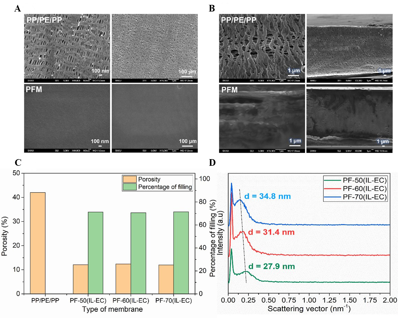
Figure 1. (A and B) FESEM images of PP/PE/PP and pore-filing membranes at surface and cross-section, respectively; (C) porosity and percentage of filling of PF-70(IL-EC) membrane; (D) SAXS curves of pore-filling membranes at various IL concentration. EC: Ethylene carbonate; IL: ionic liquid; PFM: pore-filling membrane; PP/PE/PP: polypropylene/polyethylene/polypropylene; SAXS: small angle X-ray scattering.
The phase separation behaviors of PF membranes at different concentrations of IL-EC mixtures were authenticated by SAXS profiles, as presented in Figure 1D. Because there is a significant difference in chemical compatibility between PAES main chain and PEG segments with the IL-EC mixture, the PEG conducting regions were created and separated from the PAES non-conducting area, as described in Figure 2A. The dimension of the conducting region increased with increasing IL-EC amount as PEG has high compatibility with IL-EC. Among them, the PF-70(IL-EC) membrane had the largest conducting region with a size of 34.8 nm, which facilitates Li transport in the membrane. In this study, the IL-EC content was increased up to 70 wt.% with the aim of enhancing conductivity via the formation of large Li-conductive domains and ensuring that the final physical state of the membrane is solid. However, when the IL-EC content was beyond 70 wt.%, it resulted in the liquid state of PAES-g-2PEG/IL-EC, and thus it could be leaked out of the pores and lead to polysulfide diffusion during charge/discharge cycling. This negatively affects Li-transport and battery performance.
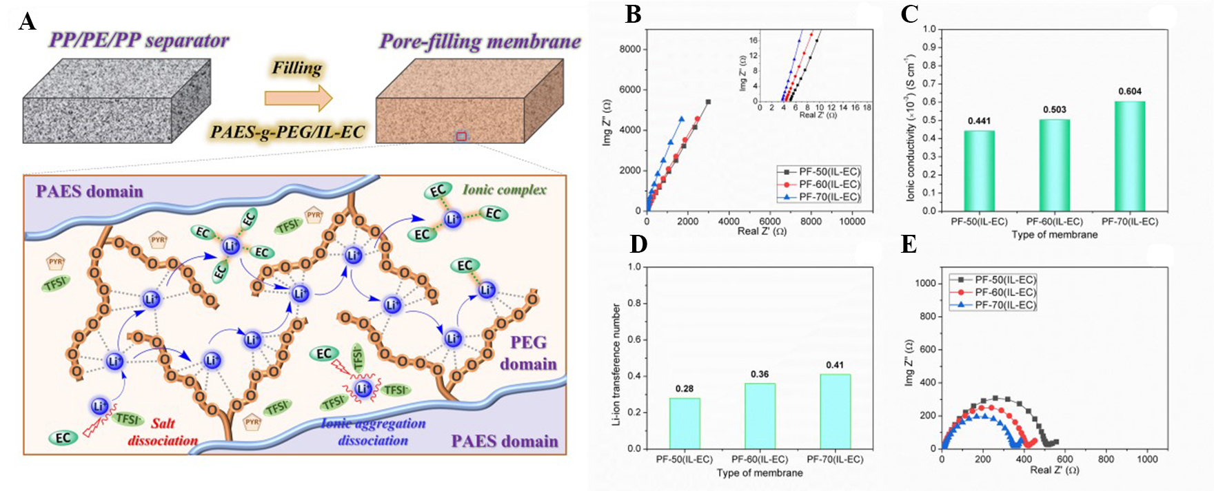
Figure 2. (A) Illustration of the Li-ion transport mechanism in conductive PEG/IL-EC domains; (B) Nyquist plot; (C) ionic conductivity; (D) lithium-ion transference number; (E) interfacial resistance of pore-filling membrane at various (IL-EC) concentrations. EC: Ethylene carbonate; IL: ionic liquid; PAES: poly(arylene ether sulfone); PEG: poly(ethylene glycol); PP/PE/PP: polypropylene/polyethylene/polypropylene.
Lithium transporting ability
To investigate Li transporting ability, σ, tLi+, and Ri of PFM were investigated and shown in Figure 2. The complex impedance plots of the prepared PF membranes at various IL-EC contents (50, 60, and 70 wt.%) were detected, as exhibited in Figure 2B. Accordingly, the σ of the PF membranes with various IL-EC contents was calculated and mentioned in Figure 2C. The introduction of the IL-EC mixture into the PF membranes resulted in a considerable improvement in σ due to improved ionic clusters, which facilitated Li migration in the membrane [Figure 1D]. Additionally, the presence of IL as a plasticizer offers more intense motion of PEG segments, which results in numerous etheric oxygen coordination sites for Li-ion transport. Consequently, the PF-70(IL-EC) membrane at the highest IL-EC content has the highest σ (~0.604 ×
The tLi+ is also a key factor in estimating the contribution of Li-ion amount on σ, which notably affects the battery performance in association with concentration polarization during the charge/discharge process. The tLi+ of prepared PFM was calculated from CA and impedance profiles [Supplementary Figure 4], and the determined values are indicated in Figure 2D[35]. The tLi+ increased from 0.28 to 0.41 at room temperature when IL-EC content was increased from 50 to 70 wt.%. The increase in tLi+ was attributed to the synergic effect of IL and EC on the PEG segment and LiTFSI dissociation. While the IL provides conductive pathways for Li-ion transport, the high dielectric constant EC additive (ε = 89) accelerates the dissociation of both LiTFSI and ionic aggregation to create a large number of mobile Li-ions to coordinate with etheric groups of PEG segments in large conducting domains [Figure 2A]. This indicated that the introduction of PAES-g-2PEG filler containing IL-EC was beneficial for transferring Li-ions in the PFM. Therefore, the
The effect of the IL/EC ratio on σ and tLi+ was investigated and presented in Supplementary Figure 5. The optimized IL/EC weight ratio was figured out at 7:3, where both σ and tLi+ were the highest because of the enhanced single Li+ ion conduction by [Li+(EC)x, (x = 1 - 5)] complexes and Li+ ion migration along the mobile PEG chains with coordinated interaction in conductive domains. However, the Li-ion conduction at higher EC concentrations (beyond 30 wt.%) decreased because the Li-ion migration is hindered by the formation of [Li+(EC)x, (x > 5)] ionic atmosphere (Li-ions are surrounded by a large number of EC) and low molecular mobility of PEG segments.
Figure 2E presents the Ri of the prepared PF membranes at different IL-EC contents. Similarly, the prepared PF membranes showed decreasing Ri with increasing IL-EC content. Li-ion transport on the surface membrane due to the presence of a thin PAES-g-2PEG/IL-EC layer (~5 - 8 µm) [Figure 1B] endowed the PF-70(IL-EC) membrane containing the highest IL-EC content with the lowest Ri (~350 Ω). This ensures easy migration of the Li-ions at interfaces between the membrane and two electrodes.
Mechanical and thermal stability
Among the essential requirements for solid electrolyte membranes in practical LSBs, flexible electrolyte membranes with the high tensile strength are expected to prevent Li-dendrite formation during cycling. Stress vs. strain curves and modulus of the PF membrane were also obtained, as presented in Figure 3A and Supplementary Figure 6, respectively. The PF-70(IL-EC) membrane had a significant increase in both tensile strength and elongation at break after filling into the PP/PE/PP substrate when compared to the pristine PAES-g-2PEG/70(IL-EC) membrane. As a result of the reinforced mechanical strength of the PP/PE/PP substrate, the PF-70(IL-EC) membrane achieved a high tensile strength of approximately 200 MPa, an elongation at failure of about 65%, and a modulus of 8.28 MPa. These values are comparable to those of the porous PP/PE/PP substrate, which has a tensile strength of around 210 MPa, an elongation at failure of approximately 55%, and a modulus of 8.56 MPa. The PF-70(IL-EC) membrane can simultaneously provide both high Li-ion conduction (σ = 0.604 × 10⁻³ S cm-1 and tLi+ = 0.41) and excellent mechanical strength

Figure 3. (A) Stress-strain curves; (B) flexibility test; (C) TGA curves; (D) thermal shrinkage of PP/PE/PP and PF-70(IL-EC) membrane. EC: Ethylene carbonate; IL: ionic liquid; PAES-g-2PEG: poly(arylene ether sulfone)-graft-dual poly(ethylene glycol); PP/PE/PP: polypropylene/polyethylene/polypropylene; TGA: thermogravimetric analyzer.
The outstanding thermal stability of the electrolyte membrane is another important requirement to reduce the explosion risk for the battery. Accordingly, the thermal stability of the PF solid electrolytes was also examined by TGA analysis, as displayed in Figure 3C. The PF-70(IL-EC) membrane shows a high thermal decomposition temperature of up to ~200 °C. The weight loss started at ~200 °C, which is attributed to the thermal decomposition of the bonding between PEG side chains and the PAES backbone. The decomposition of PAES main chains occurred at ~400 °C. The thermal dimensional stability of the
Electrochemical and interfacial stability
Figure 4A presents the electrochemical potential window of the PF-70(IL-EC) membrane, which was measured using LSV at 1.0 mV s-1 sweep rate at room temperature. The PF-70(IL-EC) membrane showed an electrochemical potential window (4.60 V vs. Li/Li+) suitable for LSB applications.

Figure 4. (A) Linear sweep voltammetry curve; (B) lithium plating/stripping test with 500 h cycling at 0.25 mA cm-2; (C) interfacial resistance before and after plating/stripping test; (D) morphology of Li surface before and after 500 h cycling test of the cell using
To investigate interfacial stability, the plating/stripping cycle investigation was employed on a Li/PFM/Li cell assembled with the PF-70(IL-EC) membrane at 0.25 mA cm-2 current density with ~500 h cycles, as inhibited in Figure 4B. The overpotential of the Li/PFM/Li cell did not change and was quite stable during plating/stripping tests. After 500 h cycling, the Li/PFM/Li cell showed a small overpotential of around
Additionally, the morphological characteristics of the Li surface before and after 500 h cycling were investigated using FESEM analysis, as presented in Figure 4D. The Li surface in the Li/PFM/Li cell after the plating/tripping test was still as smooth as the pristine Li surface. These results showed that the
X-ray photoelectric spectroscopy (XPS) was applied to investigate the compositional changes in the Solid electrolyte interphase (SEI) on the Li anode surface before and after the 500 h plating/stripping test
Cell performance
To investigate the use of a PF-70(IL-EC) membrane in LSBs, the charge/discharge capacity, rate capability, and cycling performance of a Li/PFM/S cell assembled with the PF-70(IL-EC) membrane were measured, and these results are indicated in Figure 5. The charge/discharge curves of the Li/PFM/S cell at a variety of C-rates, such as 0.1, 0.5, 1, and 2 C, are presented in Figure 5A. The specific discharge capacity of the Li/PFM/S cell increased from 657.3 mAh g-1 to 855.7 mAh g-1 with the change of C-rate from 2 to 0.2 C. At

Figure 5. (A) Charge/discharge profiles; (B) rate-capability of Li/PFM/S cell using PF-70(IL-EC) membrane at various C-rates; (C) cyclic stability of Li/PFM/S cell using PF-70(IL-EC) membrane at 0.2 C. EC: Ethylene carbonate; IL: ionic liquid; Li lithium; PFM: pore-filling membrane.
On the other hand, the cycling performance of the assembled Li/PFM/S cell at 0.2 C was employed over 200 cycles. As displayed in Figure 5C, the assembled Li/PFM/S cells showed good cycle stability with a specific capacity of 812.9 mAh g-1, which preserved 95% of the initial discharge capacity after 200 cycles. The pore-filled electrolyte [PF-70(IL-EC)] enables a superior LSB performance because this membrane has not only high σ (~0.601 mS cm-1) along with rather high tLi+ (~0.41) [Figure 1] but also high interfacial stability with Li anode [Figure 4], which can effectively prevent the formation of an unstable SEI layer on the Li electrode after the charging process. This results in the facile Li+ transport to the cathode in the discharge process and thus induces high discharge capacity. In addition, the PF-70(IL-EC) membrane with the high tensile strength (~200 MPa) and high flexibility [Figure 3] positively contributes to suppressing the Li-dendrite growth during charge/discharge cycling. This result leads to the excellent cyclic stability of Li/PFM/S cells assembled with PF-70(IL-EC) membrane.
CONCLUSIONS
In this study, PFMs were successfully prepared by the introduction of PAES-g-2PEG/(IL-EC) into porous PP/PE/PP substrates with a high filling percentage (above 70%). The PF membranes both exhibited improved Li-ion conduction (σ = 0.604 mS cm-1 and tLi+ = 0.41) and high mechanical stability with a
DECLARATIONS
Authors’ contributionsConceptualization, methodology, investigation, and writing-original draft preparation: Le Mong A, Ahn Y
Validation and data curation: Le Mong A, Ahn Y, Puttaswamy R, Kim D
Formal analysis: Le Mong A, Kim D
Writing-review and editing, visualization, supervision, project administration, and funding acquisition: Kim D
Availability of data and materialsThe data supporting our findings can be found in the Supplementary Information.
Financial support and sponsorshipThis research was supported by the National Research Foundation of Korea (NRF 2018M3D1A1058624) and the Brain Pool Program through the National Research Foundation of Korea (NRF 2019H1D3A1A02071097) funded by the Ministry of Science and ICT.
Conflicts of interestAll authors declared that there are no conflicts of interest.
Ethical approval and consent to participateNot applicable.
Consent for publicationNot applicable.
Copyright© The Author(s) 2023.
REFERENCES
1. Crawford AJ, Huang Q, Kintner-meyer MC, et al. Lifecycle comparison of selected Li-ion battery chemistries under grid and electric vehicle duty cycle combinations. J Power Sources 2018;380:185-93.
2. Bi Z, Guo X. Solidification for solid-state lithium batteries with high energy density and long cycle life. Energy Mater 2022;2:200011.
3. Shin H, Baek M, Gupta A, Char K, Manthiram A, Choi JW. Recent progress in high donor electrolytes for lithium-sulfur batteries. Adv Energy Mater 2020;10:2001456.
4. Heidari AA, Mahdavi H. Recent development of polyolefin-based microporous separators for Li-Ion batteries: a review. Chem Rec 2020;20:570-95.
5. Duan J, Tang X, Dai H, et al. Building safe lithium-ion batteries for electric vehicles: a review. Electrochem Energy Rev 2020;3:1-42.
6. Le Mong A, Kim D. Acceleration of selective lithium ion transport of PAES-g-2PEG self-assembled flexible solid-state electrolytes for lithium secondary batteries. Energy Stor Mater 2022;47:394-407.
7. Lucero M, Qiu S, Feng Z. In situ characterizations of solid-solid interfaces in solid-state batteries using synchrotron X-ray techniques. Carbon Energy 2021;3:762-83.
8. Li S, Zhang W, Zheng J, Lv M, Song H, Du L. Inhibition of polysulfide shuttles in Li-S batteries: modified separators and solid-state electrolytes. Adv Energy Mater 2021;11:2000779.
9. Samson AJ, Hofstetter K, Bag S, Thangadurai V. A bird’s-eye view of Li-stuffed garnet-type Li7La3Zr2O12 ceramic electrolytes for advanced all-solid-state Li batteries. Energy Environ Sci 2019;12:2957-75.
10. Thangadurai V, Narayanan S, Pinzaru D. Garnet-type solid-state fast Li ion conductors for Li batteries: critical review. Chem Soc Rev 2014;43:4714-27.
11. Ye L, Li X. A dynamic stability design strategy for lithium metal solid state batteries. Nature 2021;593:218-22.
12. Lewis JA, Cortes FJQ, Boebinger MG, et al. Interphase morphology between a solid-state electrolyte and lithium controls cell failure. ACS Energy Lett 2019;4:591-9.
13. Xie H, Yang C, Fu KK, et al. Flexible, scalable, and highly conductive garnet-polymer solid electrolyte templated by bacterial cellulose. Adv Energy Mater 2018;8:1703474.
14. Xu R, Xia X, Zhang S, Xie D, Wang X, Tu J. Interfacial challenges and progress for inorganic all-solid-state lithium batteries. Electrochimica Acta 2018;284:177-87.
15. Plylahan N, Kerner M, Lim D, Matic A, Johansson P. Ionic liquid and hybrid ionic liquid/organic electrolytes for high temperature lithium-ion battery application. Electrochimica Acta 2016;216:24-34.
16. Montanino M, Moreno M, Carewska M, et al. Mixed organic compound-ionic liquid electrolytes for lithium battery electrolyte systems. J Power Sources 2014;269:608-15.
17. Bi S, Banda H, Chen M, et al. Molecular understanding of charge storage and charging dynamics in supercapacitors with MOF electrodes and ionic liquid electrolytes. Nat Mater 2020;19:552-8.
18. Francis CFJ, Kyratzis IL, Best AS. Lithium-ion battery separators for ionic-liquid electrolytes: a review. Adv Mater 2020;32:e1904205.
19. Jung HY, Mandal P, Jo G, et al. Modulating ion transport and self-assembly of polymer electrolytes via end-group chemistry. Macromolecules 2017;50:3224-33.
20. Li C, Xue P, Chen L, Liu J, Wang Z. Reducing the crystallinity of PEO-based composite electrolyte for high performance lithium batteries. Compos Part B: Eng 2022;234:109729.
21. Chopade SA, Au JG, Li Z, Schmidt PW, Hillmyer MA, Lodge TP. Robust polymer electrolyte membranes with high ambient-temperature lithium-ion conductivity via polymerization-induced microphase separation. ACS Appl Mater Interfaces 2017;9:14561-5.
22. Le Mong A, Shi QX, Jeon H, Ye YS, Xie XL, Kim D. Tough and flexible, super ion-conductive electrolyte membranes for lithium-based secondary battery applications. Adv Funct Mater 2021;31:2008586.
23. Li S, Zhang SQ, Shen L, et al. Progress and perspective of ceramic/polymer composite solid electrolytes for lithium batteries. Adv Sci 2020;7:1903088.
24. Li L, Wang M, Wang J, et al. Asymmetric gel polymer electrolyte with high lithium ion conductivity for dendrite-free lithium metal batteries. J Mater Chem A 2020;8:8033-40.
25. Li Z, Li T, Deng Y, et al. 3D porous PTFE membrane filled with PEO-based electrolyte for all solid-state lithium-sulfur batteries. Rare Met 2022;41:2834-43.
26. Hu J, He P, Zhang B, Wang B, Fan L. Porous film host-derived 3D composite polymer electrolyte for high-voltage solid state lithium batteries. Energy Stor Mater 2020;26:283-9.
27. Seo Y, Jung Y, Park M, Kim D. Solid polymer electrolyte supported by porous polymer membrane for all-solid-state lithium batteries. J Membr Sci 2020;603:117995.
28. Ahn Y, Kim D. Ultra-low vanadium ion permeable electrolyte membrane for vanadium redox flow battery by pore filling of PTFE substrate. Energy Stor Mater 2020;31:105-14.
29. Jeon H, Kim D. Simultaneous establishment of high conductivity and mechanical stability via pore-filling of porous PTFE substrate with poly(ethylene glycol) and ionic liquid for lithium secondary battery. J Membr Sci 2021;624:119029.
30. Park G, Kim D. Porous PTFE reinforced SPEEK proton exchange membranes for enhanced mechanical, dimensional, and electrochemical stability. Polymer 2021;218:123506.
31. Ahn Y, Kim D. High energy efficiency and stability of vanadium redox flow battery using pore-filled anion exchange membranes with ultra-low V4+ permeation. J Ind Eng Chem 2022;110:395-404.
32. Zhang T, Tian T, Shen B, Song Y, Yao H. Recent advances on biopolymer fiber based membranes for lithium-ion battery separators. Compos Commun 2019;14:7-14.
33. Bhatt MD, Cho M, Cho K. Interaction of Li+ ions with ethylene carbonate (EC): density functional theory calculations. Appl Surf Sci 2010;257:1463-8.
34. Bhatt MD, Cho M, Cho K. Conduction of Li+ cations in ethylene carbonate (EC) and propylene carbonate (PC): comparative studies using density functional theory. J Solid State Electrochem 2012;16:435-41.
Cite This Article
Export citation file: BibTeX | RIS
OAE Style
Le Mong A, Ahn Y, Puttaswamy R, Kim D. Pore filled solid electrolytes with high ionic conduction and electrochemical stability for lithium sulfur battery. Energy Mater 2023;3:300035. http://dx.doi.org/10.20517/energymater.2023.20
AMA Style
Le Mong A, Ahn Y, Puttaswamy R, Kim D. Pore filled solid electrolytes with high ionic conduction and electrochemical stability for lithium sulfur battery. Energy Materials. 2023; 3(4): 300035. http://dx.doi.org/10.20517/energymater.2023.20
Chicago/Turabian Style
Le Mong, Anh, Yeonho Ahn, Rangaswamy Puttaswamy, Dukjoon Kim. 2023. "Pore filled solid electrolytes with high ionic conduction and electrochemical stability for lithium sulfur battery" Energy Materials. 3, no.4: 300035. http://dx.doi.org/10.20517/energymater.2023.20
ACS Style
Le Mong, A.; Ahn Y.; Puttaswamy R.; Kim D. Pore filled solid electrolytes with high ionic conduction and electrochemical stability for lithium sulfur battery. Energy Mater. 2023, 3, 300035. http://dx.doi.org/10.20517/energymater.2023.20
About This Article
Special Issue
Copyright

Data & Comments
Data


 Cite This Article 7 clicks

 Like This Article 13
likes
Like This Article 13
likes


Comments
Comments must be written in English. Spam, offensive content, impersonation, and private information will not be permitted. If any comment is reported and identified as inappropriate content by OAE staff, the comment will be removed without notice. If you have any queries or need any help, please contact us at support@oaepublish.com.