
Highly fluorinated co-solvent enabling ether electrolyte for high-voltage lithium ion batteries with graphite anode
 0
0
Abstract
Conventional ether electrolytes are generally considered unsuitable for use with graphite anodes and high-voltage cathodes due to their co-intercalation with graphite and poor oxidation stability, respectively. In this work, a highly fluorinated ether molecule, 1,1,1-trifluoro-2-[(2,2,2-trifluoroethoxy) methoxy] ethane (TTME), is introduced as a co-solvent into the conventional ether system to construct a fluorinated ether electrolyte, which not only avoids the co-intercalation with graphite but also is compatible with high-voltage cathodes. Li||graphite half-cells using the fluorinated ether electrolyte deliver stable cycling with a capacity retention of 91.7% for 300 cycles. Moreover, LiNi0.8Co0.1Mn0.1O2 (NCM811)||graphite and LiCoO2 (LCO)||graphite full-cells (cathode loadings are ≈3 mAh/cm2) with the fluorinated ether electrolyte show capacity retentions of > 90% over 200 cycles with a charge cut-off voltage of 4.4 V and > 97% for 100 cycles with a charge cut-off voltage of 4.5 V, respectively. The dense and firm solid electrolyte interphase (SEI) and cathode electrolyte interphase (CEI) formed by the fluorinated ether electrolyte on the anode and cathode, respectively, are key to excellent cell performance. These results have significance for the subsequent application of ether electrolytes for high-voltage lithium ion batteries (up to 4.5 V) with graphite anodes.
Keywords
INTRODUCTION
Lithium ion batteries (LIBs) have been widely used in the field of consumer electronics due to their advantages of high energy density and long cycle life and have shown great development prospects in the field of electric vehicles[1,2]. Graphite anodes combined with high-voltage cathode materials, such as layered oxides, including LiCoO2 (LCO) and LiNi0.8Co0.1Mn0.1O2 (NCM811), are currently widely used in high-energy-density commercial LIBs[3-6]. The most widely used electrolyte system is composed of lithium hexafluorophosphate (LiPF6) as the lithium salt, ethylene carbonate (EC), and other linear carbonates, such as diethyl carbonate (DEC), dimethyl carbonate (DMC), etc., as solvents, and with different functional additives[7,8]. However, the use of these electrolytes under some harsh conditions is limited due to high viscosity of carbonates, high melting point of EC, and poor thermal stability of LiPF6[9,10]. Thus, a new research direction has emerged to design an electrolyte without EC that can quickly transfer lithium ions and is suitable for use over a wider temperature range (0-60 °C).
Ether compounds are promising electrolyte solvents and have been widely used in different battery systems, such as those based on lithium metal anodes and silicon anodes, due to their low melting point, low viscosity, and good reduction stability[11]. However, reports in the literature suggested that ether electrolytes are not compatible with graphite anodes[12-14]. It has been reported that ether electrolytes lead to solvent co-intercalation, graphite exfoliation, and electrolyte decomposition, with which the cells show decreased Coulombic efficiency and poor cycle stability. In recent years, due to the rapid development of hydrofluoroethers (HFEs) used as co-solvents in other anode systems[15-18], researchers have turned their attention to the possibility of designing ether electrolytes that are suitable for graphite electrodes[19]. Some electrolytes based on fluorinated ether co-solvents have been reported to deliver stable cycling of graphite anodes[12,20,21]. In these reports, in addition to the regulation of the solvation structure, the formation of a stable anion-based solid electrolyte interphase (SEI) film on the graphite surface is the key to suppressing the co-intercalation of solvent molecules with graphite. This, in turn, helps maintain their functionality and performance over extended cycles[22-24].
In this work, a fluorinated ether co-solvent, 1,1,1-trifluoro-2-[(2,2,2-trifluoroethoxy) methoxy] ethane (TTME), was introduced to the conventional ether electrolyte system comprising of 1,2-dimethoxyethane (DME) and lithium bis(fluorosulfonyl)imide (LiFSI) to form a fluorinated ether-based electrolyte. On the one hand, the fluorinated ether electrolyte can generate a stable SEI on the surface of the anode to inhibit the co-intercalation, protect the structure of graphite, and inhibit the decomposition of the electrolyte. On the other hand, due to the high degree of fluorination of TTME, the overall oxidation stability of the fluorinated ether electrolyte is improved, making it less susceptible to oxidative degradation.
The EC/DEC carbonate electrolyte containing 1 wt.% vinylene carbonate (VC) and 1 wt.% 1,3-propanesultone (PS), which has been reported previously by our group to exhibit good performance for high-voltage full-cell cycling, was used as a control electrolyte[25]. The results show that the fluorinated ether electrolyte system behaves better stabilities than the carbonate electrolyte system against both high-voltage layered oxides cathodes and graphite anodes. The NCM811||graphite cells with the fluorinated ether electrolyte exhibit stable cycling at a cut-off voltage of 4.4 V, maintaining capacity retention greater than 90% after 200 cycles at 0.33 C. When the fluorinated ether electrolyte is applied to the LCO||graphite cells with a cut-off voltage of 4.5 V, the cells deliver capacity retention of 97% after 100 cycles at 0.33 C. Moreover, the large-capacity NCM811||graphite pouch cells (1,780 mAh) using the fluorinated ether electrolyte perform better cycling performance than the carbonate electrolyte at both room temperature and elevated temperature.
EXPERIMENTAL DETAILS
Electrolytes and cells preparation, density functional theory (DFT) calculation
All the reagents, including lithium salts and solvents with a purity of above 99.9%, were provided by Capchem Technology Co., Ltd. (Shenzhen, China). The fluorinated ether electrolyte was formed by dissolving 374 mg LiFSI in 1 mL mixed solvent with TTME and DME at a volume ratio of 4:1. The final concentration of lithium salt was 1.4 mol/L. A conventional ether electrolyte containing DME with
Electrochemical measurements
Electrochemical measurements were carried out using 2032-type coin cells or pouch cells. Dry NCM811||artificial graphite (AG) pouch cells (with 1,780 mAh capacity) were provided by Capchem Technology Co. Ltd. For coin cells, all the electrode plates, except lithium metal, were obtained from pouch cell disassembly. The active material loading of NCM811 was 3.13 mAh/cm2, and the loading of LCO was 2.96 mAh/cm2. All coin cells were fabricated in an argon (Ar)-filled glovebox, with 50 μL electrolyte and one layer of Celgard 2400 separator used in each cell. For pouch cells, the dry pouch cells were cut and then dried at 85 °C under vacuum for 24 h. The pouch cells were then injected with 5.8 g of the fluorinated ether electrolyte (or control electrolytes) and were then sealed in an Ar-filled glove box. The commercial-standard formation and aging processes were applied to the assembled pouch cells before further electrochemical measurements[26].
Cyclic voltammetry (CV) was performed over a voltage range from an open circuit voltage to 0.01 V and then to 2.0 V. Electrochemical impedance spectrometry (EIS) was conducted in the frequency range of
In situ gas analysis
Differential electrochemical mass spectrometry (DEMS) experiments were carried out with a Hiden Analytical mass spectrometer system (HPR20, UK). Filtered high-purity Ar gas was used as the carrier gas. The electrodes were prepared by mixing active materials (graphite or NCM811), super P, and polyvinylidene difluoride at a weight ratio of 80:10:10. The pastes were cast onto Celgard 2400 separators to form electrodes. The mass loading of graphite was controlled at ≈30 mg/cm2, and the mass loading of NCM811 was ≈18 mg/cm2. Three layers of glass fiber (MA-EN-SE-01, Canrd) were used as the separators. Li||NCM811 cells were cycled from 2.5 to 5.0 V, and Li||graphite cells were cycled from 2.5 to 0 V.
Characterizations
After 100 times cycling, the cells were disassembled in a glove box, and all the electrodes were washed with the corresponding solvent (DME for TTME-d and DME-d systems, DEC for carbonate system) three times before characterizations. The samples were transferred for characterizations under an Ar atmosphere (without air contact). X-ray photoelectron spectroscopy (XPS) with a 200 μm X-ray gun source was performed on an Escalab Xi+ (Thermo Avantage), and the C 1s signal of 284.8 eV was set as an internal standard to correct the binding energies. The morphologies of graphite and cathode electrodes were characterized with a field emission scanning electron microscope (SEM) (TESCAM MIRA3). Aberration-corrected high-angle annular dark field-scanning transmission electron microscopy (HAADF-STEM) images were taken on Titan Cubed Themis G2 300. X-ray diffraction (XRD) patterns were characterized with Rigaku SmartLab equipped using a Cu Kα radiation source in the 2θ range from 0 to 90°, with a speed of 10°/min.
RESULTS AND DISCUSSION
Through the DFT calculation, the highest occupied molecular orbital (HOMO) energy value and the lowest unoccupied molecular orbital (LUMO) energy value of the different solvents and additives were investigated. As shown in Figure 1, the LUMO energy level of TTME (1.491 eV) is slightly lower than that of DME (2.316 eV) but still higher than that of general carbonate solvents and additives, indicating its strong reduction stability on the anode side. In addition, due to the high fluorine (F) substitution of the TTME molecule, its HOMO energy level (-7.758 eV) is obviously lower than those of traditional ether molecules and even lower than that of some carbonate solvents and additive molecules (DEC: -7.2779 eV, VC: -6.999 eV). This shows that the substitution of hydrogen (H2) by F can improve the oxidation stability of ether molecules.
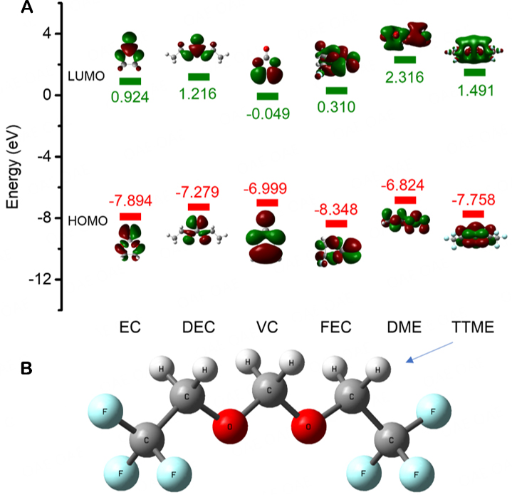
Figure 1. (A) LUMO and HOMO values of DME, TTME, and some carbonates. (B) Schematic molecular structure of TTME.
For DME, although its reduction stability is the best among these solvents and additives, it would easily co-intercalate with graphite during charge/discharge, resulting in the stripping of graphite and the decomposition of the electrolyte[12-14]. This problem can be clearly seen from the CV curves in Figure 2A. As the discharge progresses, the CV curve of the Li||graphite half-cell using the ether electrolyte begins to show peaks when the voltage drops to ≈1.2 V, and as the discharge process continues, the peaks become larger, and the shape of the curves is irregular. During the delithiation process, the internal reactions of the cell with the ether electrolyte are also extremely unstable. As the voltage increases, small peaks not for the charge-discharge platform continue to appear in the CV curve. In the subsequent four cycles, such irregular small peaks are always observed, and none of them overlaps, indicating that various side reactions constantly occur. This shows that DME cannot form a stable SEI film on graphite when it is solely used, and the co-intercalation process with graphite leads to the collapse of the graphite structure and the decomposition of the electrolyte.
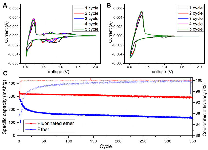
Figure 2. Performance of Li||graphite half-cells with different electrolyte systems: CV curves using (A) conventional ether and (B) fluorinated ether electrolytes; (C) Cycling performance using conventional ether and fluorinated ether electrolytes.
The electrolyte developed in this work contains two ethers, DME and TTME, and the addition of TTME as the co-solvent prevents the occurrence of the above problem. Considering the entire electrolyte system, the addition of TTME weakens the interaction between DME solvent and Li+ ions, enhancing the desolvation process of Li+ ions, which would be beneficial for inhibiting the co-intercalation with graphite[19]. As can be seen from the CV curves of the Li||graphite half-cell using the fluorinated ether electrolyte in Figure 2B, except for the process of generating SEI during the first cycle of discharge, the CV curves of the overall five cycles have a high degree of coincidence. This indicates that the SEI generated in the first cycle has a good protective effect on the electrode structure and can prevent the delamination of the graphite structure and thus inhibit the decomposition of the electrolyte. These results indicate that the cell using the fluorinated ether electrolyte has a high degree of cycle reversibility on the graphite anode.
The electrochemical performance of the Li||graphite half cells using the ether and fluorinated ether electrolytes was further investigated. As shown in Figure 2C, the Li||graphite half-cell using the fluorinated ether electrolyte delivers 91.7% capacity retention after 300 cycles and 88.7% capacity retention after 350 cycles. In contrast, the Li||graphite half-cell using the ether electrolyte could not release the full capacity even at the beginning of the cycle and experiences a rapid capacity decay. After 100 cycles, the capacity of the cell with the ether electrolyte is less than 50% of its original capacity. The Nyquist plots in Supplementary Figure 1 show that the impedance increase in the cell with the fluorinated ether electrolyte is much smaller than that in the cell with the ether electrolyte. These results further prove that in Li||graphite cells, the addition of TTME as a co-solvent significantly improves the compatibility between ethers and graphite anodes. At the same time, the results indicate that a stable SEI can be generated on the graphite anode with the fluorinated ether electrolyte so that the cell has stable cycling for more than 300 cycles.
On the basis of the good cycling performance of Li||graphite half cells, different electrolytes were applied to high-voltage full-cells with two different commercial cathode plates (LCO and NCM811). For better comparison, the carbonate electrolyte (1 mol/L LiPF6 in a mixture of EC/DEC (30:70, wt./wt.) with 1 wt.% VC and 1 wt.% PS) with good cycle performance at high voltage was introduced as a control sample. It can be seen from Figure 3 that the cycle performance of the cells with the fluorinated ether electrolyte for both the high-voltage cathodes is much better than those of the cells with the two controls.
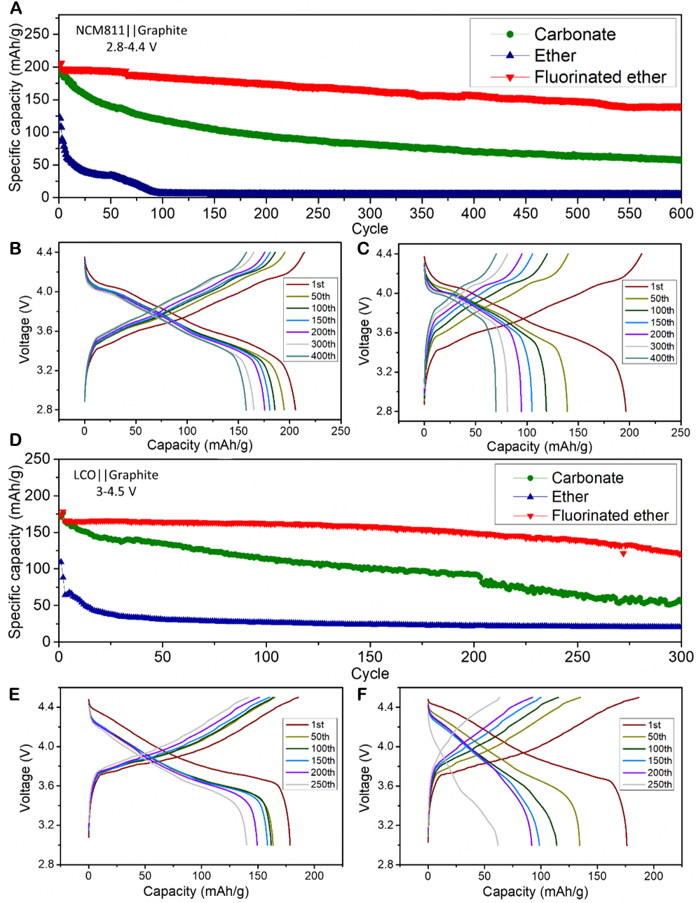
Figure 3. Overall performance of full-cells with different cathodes: (A) Cycling performance of NCM811||graphite cells with different electrolyte systems; Charge-discharge curves of NCM811||graphite cells with (B) fluorinated ether and (C) carbonate electrolytes; (D) Cycling performance of LCO||graphite cells with different electrolyte systems; Charge-discharge curves of LCO||graphite cells with (E) fluorinated ether and (F) carbonate electrolytes.
As shown in Figure 3A, for the NCM811||graphite full cells (between 2.8 V and 4.4 V), the capacity retention rate of the cell with the fluorinated ether electrolyte reaches 94.7% after 100 cycles, > 90% after 200 cycles, and 84% after 300 cycles and drops to ≈70% after 600 cycles. It even can work over 1,000 cycles without failure, and the terminal capacity after 1,000 cycles is about 50% of the initial capacity
Furthermore, the performance of the cells using the LCO cathodes with different electrolytes was investigated at a higher cut-off voltage (4.5 V) to further study the electrolyte compatibility with high-voltage cathodes. As shown in Figure 3D, for the LCO||graphite full cells, the capacity retention of the cell with the fluorinated ether is higher than 97% after 100 cycles, and the cell can still cycle stably with a capacity retention of 71.9% after 300 cycles. The capacity of the cell with the ether electrolyte cannot be fully exerted under these conditions either. The charge specific capacity and discharge specific capacity of the first cycle are 164 mAh/g and 109 mAh/g, respectively, and the Coulombic efficiency of the cell in the first cycle is low (66.9%). The side reactions that occur on both the cathode and anode make the cell with the ether electrolyte rapidly invalid. The cell with the carbonate electrolyte has a capacity retention rate of 69.3% after 100 cycles, which is also much lower than that of the cell with the fluorinated ether electrolyte. After about 200 cycles, the cell experiences unstable fluctuations, and the capacity decreases at a faster rate.
It can also be seen from the charge-discharge curves in Figure 3E and F that the charge-discharge platform of the cell with the carbonate electrolyte basically disappears after 150 cycles. The possible reasons for this are that the additives VC and PS and even some solvents in the carbonate electrolyte are excessively decomposed under the high-voltage environment of 4.5 V, which results in the capacity fade of the cell. At the same time, due to the absence of a stable cathode electrolyte interphase (CEI) layer formation during the first charge/discharge cycle, the continuous destruction of the layered LCO structure is one of the main reasons for the capacity decay. These results show that even the EC/DEC electrolyte with the addition of additives (1% VC and 1% PS) cannot maintain a stable cycle under the severe 4.5 V high-voltage condition, which highlights the excellent performance of the fluorinated ether electrolyte for high-voltage application.
Moreover, large-capacity commercial NCM811||graphite pouch cells (1,780 mAh) were assembled to further evaluate the performance of the fluorinated ether electrolyte. The pouch cells were subjected to the cycle measurements at room temperature (25 °C) and high temperature (45 °C), and DCIR was measured during cycling. As shown in Figure 4A, as the voltage range decreases, the cycle performance of the pouch cell with the carbonate control electrolyte is significantly improved [Figure 3A]. Interestingly, the cycle performance of the pouch cell with the fluorinated ether electrolyte is still better than that of the pouch cell with the carbonate electrolyte. Through the statistical analysis of all the measured pouch cells, it is determined that the average first-cycle Coulombic efficiency of the cells using the fluorinated ether electrolyte is 88.9%, which is slightly higher than that of the cells using the carbonate electrolyte (88.3%). Although the cells using both two electrolytes maintain a capacity retention rate of more than 90% in the first 300 cycles, the capacity retention of the cell using the fluorinated ether electrolyte is slightly higher than that of the cell using the carbonate electrolyte.
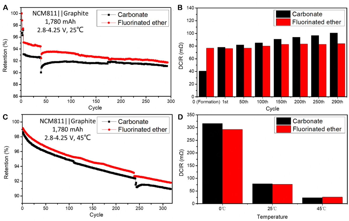
Figure 4. Overall performance of NCM811||graphite pouch cells at different temperatures: (A) Cycling performance with different electrolyte systems at 25 °C and (B) corresponding DCIR changes; (C) Cycling performance with different electrolyte systems at 45 °C; (D) DCIR of NCM811||graphite pouch cells at different temperatures.
Figure 4B shows that the DCIR of the cell with the fluorinated ether electrolyte is larger than that of the cell with the carbonate electrolyte during the formation stage, and the growth rate of DCIR of the former is much lower than that of the latter during the subsequent cycles. This indicates that in the cell with the fluorinated ether electrolyte, both the CEI on the cathode and the SEI on the anode have been formed in the formation stage, and both the interphases remain stable in the subsequent cycles, which are the key to the cycling stability of the pouch cells with the fluorinated ether electrolyte. In contrast, the DCIR of the cell with the carbonate electrolyte shows a large increase from the electrolyte assembly (formation) to the first cycle and continues to increase in the subsequent cycles. This indicates that the complete formation of CEI and SEI with this carbonate electrolyte occurs only after the completion of the first charge/discharge cycle. Moreover, the stabilities of these two interphase layers are insufficient, as the carbonate electrolyte is continuously decomposed, accompanied by the formation of new interphase layers.
Figure 4C shows that the cycle results at high temperatures (45 °C) are similar to those at room temperature and that the cell with the fluorinated ether electrolyte still has higher first-cycle Coulombic efficiency and capacity retention. In addition, it can be seen from Supplementary Figure 3 that although the initial DCIR of the cell with the fluorinated ether electrolyte is slightly higher than that of the cell with the carbonate electrolyte at 45 °C, the DCIR growth rate of the former (12.5% after 300 cycles) is smaller than that of the latter (31.1% after 300 cycles). Besides, Figure 4D presents a comparison of DCIR cycled at different temperatures, wherein it can be seen that the DCIR of the cells with the two control electrolytes increases significantly at 0 °C, which is related to the limited internal charge transfer and lithium ion migration at low temperatures. However, by comparison, the impedance value of the cell with the fluorinated ether electrolyte is still smaller than that of the cell with the carbonate electrolyte, indicating that the fluorinated ether electrolyte has application potential at low temperatures.
In order to further explore the gas production from the different components in the electrolyte during the formation of the cathode and anode interphases, DEMS measurements were conducted on the different electrolyte systems with Li||graphite and Li||NCM811 cells. As shown in Figure 5A, the Li||graphite cells using both the fluorinated ether and carbonate electrolytes periodically generate H2 as the discharge process progresses, while the cell with the ether electrolyte does not. Combined with the analysis of cell cycle performance, it can be inferred that the generation of H2 is related to the formation of the SEI on the graphite side in the fluorinated ether electrolyte. The addition of the TTME molecule enables the fluorinated ether electrolyte to effectively generate a SEI, which facilitates the migration of lithium ions towards the graphite side. The addition of film-forming additives makes the peak of H2 more noticeable in the carbonate electrolyte group, and the highest peak in the first cycle can reach 9 nmol/min. However, the ether electrolyte system does not produce H2 periodically because of the occurrence of irregular side reactions on the graphite side.
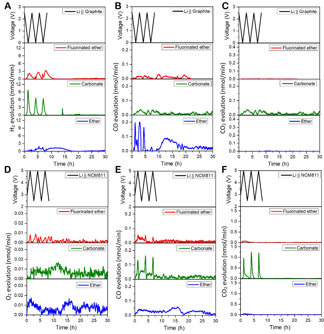
Figure 5. Gaseous evolution rates of (A) H2, (B) CO, and (C) CO2 measured in Li||graphite DEMS cells; gaseous evolution rates of
The source of H2 is the reduction of proton hydrogen in the electrolyte. Some of the proton hydrogen comes from trace amounts of water and alcohol impurities in the electrolyte, while the other part comes from the decomposition of solvents[27]. The proposed formation mechanism of H2 is displayed in
The gas generation on the cathode of the NCM811 is slightly different. Figure 5D reveals that the cells using the three electrolyte systems produce a certain amount of O2 during the high-voltage cycle. Since the amount of O2 produced is small, it is difficult to clearly observe the periodicity, but it can be seen from the overall volume that the gas production of the fluorinated ether group is much less than that of the two control groups, which confirms the excellent CEI generated on the cathode with the fluorinated ether electrolyte. It can be seen from Figure 5E that all these three electrolyte systems produce CO gas at high voltage. For the ether and fluorinated ether electrolytes, the generation of CO gas mainly comes from the decomposition of ethers at high voltage, but some differences can be seen by comparing the curves. The CO production of the fluorinated ether group is mainly concentrated in the cycle and has periodic peaks. However, more CO gas is generated in the cell with the conventional ether electrolyte, and CO continues to be generated throughout the measurement period, indicating that DME is oxidized and decomposed in large quantities at high voltage. Combining Figure 5E and F, the productions of CO and CO2 in the carbonate group are significantly higher than those in the ether and fluorinated ether groups, and there are periodic changes. The main sources of CO and CO2 are due to the oxidative decomposition of cyclic carbonates (VC and EC)[27].
In order to explore the effect of the interphase formed by different electrolytes on the cathode and anode sides, the cells, after 100 cycles in different electrolyte systems, were disassembled, and the electrodes were taken for SEM and XPS characterizations. Since the conventional ether electrolyte system is unstable at high voltage, only the electrodes with the fluorinated ether and carbonate electrolytes are selected for characterizations. Supplementary Figure 4 shows the SEM images of the cycled LCO, NCM 811, and graphite electrodes. As can be seen, the surface of the LCO electrode with the fluorinated ether electrolyte is smoother and flatter compared to that with the carbonate electrolyte, in which more LCO particles are broken. In addition, the surface of the cycled NCM811 cathode with the fluorinated ether electrolyte is clean and not covered by a thick passivation layer, while that with the carbonate electrolyte has some thick passivation layers to some extent. A similar phenomenon can be observed for the cycled graphite electrodes, and the surface of the graphite with the fluorinated ether electrolyte is smoother and flatter in comparison with that with the carbonate electrolyte.
In terms of the composition of the interphase, the fluorinated ether system produces less carbonate and more organic components on the SEI surface compared to the carbonate system [Figure 6A and B]. From the F 1s XPS spectra, it can be clearly seen that in addition to LiF, a considerable S-F peak is present in the fluorinated ether system[14]. A unique N element peak can also be seen in Supplementary Figure 5 for this system. Combined with the S 2p and N 1s spectra, it can be determined that the organic components rich in F, S, and N are responsible for the robust SEI formation in the fluorinated ether system[29]. The decomposition of the film-forming additives in the carbonate system results in the formation of a conventional SEI[7]. Although there is a certain amount of S signal due to the reduction of the additive PS, it is relatively weak compared to that obtained in the fluorinated ether system[30]. Figure 6C and D presents the XPS spectra of the cycled NCM811. It is worth noting that there is a unique CFx peak in the C 1s spectrum of the fluorinated ether system. At the same time, there is a strong peak from C-SOx in the fluorinated ether system, but the peak of the S element is too weak to be detected in the carbonate system. It can be concluded that the stable SEI and CEI formed by the fluorinated ether system are related to high contents of F and S containing organic components in the interphases.

Figure 6. C 1s, F 1s, and S 2p XPS spectra of graphite electrodes after 100 cycles with (A) fluorinated ether and (B) carbonate electrolytes; C 1s, F 1s, and S 2p XPS spectra of NCM811 electrodes after 100 cycles with (C) fluorinated ether and (D) carbonate electrolytes.
Furthermore, the STEM characterization of the cathode plates after cycling with the fluorinated ether and carbonate electrolyte systems was carried out to observe the thicknesses of the CEI formed on the cathode surfaces, and the results are displayed in Figure 7. It is evident that the CEI films formed on both the surfaces of the cycled LCO and NCM811 cathodes with the fluorinated ether electrolyte are smooth and flat, except for the occasional small gaps observed on the surface of the cycled LCO. The internal lattice structures are also clearly visible, and they are consistent with their raw layered structures
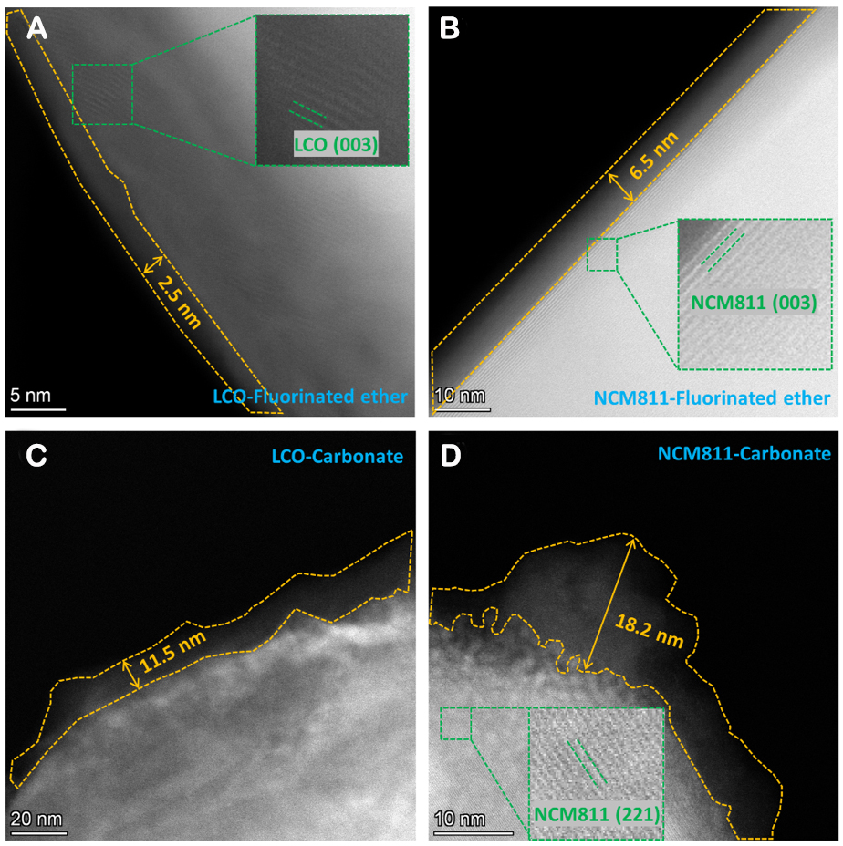
Figure 7. STEM images of cycled electrodes after 100 cycles: (A) LCO and (B) NCM811 electrodes using fluorinated ether electrolytes; STEM images of cycled (C) LCO and (D) NCM811 electrodes using carbonate electrolytes.
CONCLUSION
In this work, a highly fluorinated ether, namely TTME, was added to the DME/LiFSI electrolyte system to obtain a fluorinated ether electrolyte. This electrolyte avoided the problem of co-intercalation of DME with graphite and stabilized the performance of the Li||graphite cells (91.7% capacity retention for 300 cycles). Additionally, the electrolyte also overcame the challenge of high-voltage cathodes by providing a stable CEI. Both the NCM811||graphite cells and the LCO||graphite cells delivered excellent cycling performance at high charge cut-off voltages. Through multiple characterizations, it could be concluded that the dense and strong SEI and CEI formed by the fluorinated ether electrolyte on the anode and cathode sides, respectively, are the essential guarantee for stable cycling. These results have provided design principles for the application of ether electrolytes in high-voltage LIBs.
DECLARATIONS
Authors’ contributionsMade substantial contributions to the conception and design of the study and performed data analysis and interpretation: Wang R, Zhang G, Wang J, Lynch I, Deng Y
Performed data acquisition and provided administrative, technical, and material support: Wang H, Zhao H, Yuan M, Liu Z, Zhang T, Qian Y
Availability of data and materialsAll data are available in the manuscript and the Supplementary Material.
Financial support and sponsorshipThis work was supported by the Key-Area Research and Development Program of Guangdong Province (2020B090919001), the National Natural Science Foundation of China (22078144), and the Guangdong Natural Science Foundation for Basic and Applied Basic Research (2021A1515010138 and 2023A1515010686).
Conflicts of interestAll authors declared that there are no conflicts of interest.
Ethical approval and consent to participateNot applicable.
Consent for publicationNot applicable.
Copyright© The Author(s) 2023.
Supplementary MaterialsREFERENCES
1. Goodenough JB, Park KS. The Li-ion rechargeable battery: a perspective. J Am Chem Soc 2013;135:1167-76.
2. He X, Wang J, Jia H, et al. Ionic liquid-assisted solvothermal synthesis of hollow Mn2O3 anode and LiMn2O4 cathode materials for Li-ion batteries. J Power Sources 2015;293:306-11.
3. Li Q, Chen J, Fan L, Kong X, Lu Y. Progress in electrolytes for rechargeable Li-based batteries and beyond. Green Energy Environ 2016;1:18-42.
4. Pham HQ, Hwang EH, Kwon YG, Song SW. Approaching the maximum capacity of nickel-rich LiNi0.8Co0.1Mn0.1O2 cathodes by charging to high-voltage in a non-flammable electrolyte of propylene carbonate and fluorinated linear carbonates. Chem Commun 2019;55:1256-8.
5. Ma X, Zhang P, Zhao H, et al. LiCoO2/graphite cells with localized high concentration carbonate electrolytes for higher energy density. Liquids 2021;1:60-74.
6. Kang Y, Wang J, Wang M, et al. Multifunctional fluoroethylene carbonate for improving high-temperature performance of
7. Qian Y, Hu S, Zou X, et al. How electrolyte additives work in Li-ion batteries. Energy Stor Mater 2019;20:208-15.
8. Kang Y, Wang J, Du L, et al. Overcharge investigations of LiCoO2/graphite lithium ion batteries with different electrolytes. ACS Appl Energy Mater 2019;2:8615-24.
9. Xu K. Nonaqueous liquid electrolytes for lithium-based rechargeable batteries. Chem Rev 2004;104:4303-417.
11. Fan X, Chen L, Ji X, et al. Highly fluorinated interphases enable high-voltage Li-metal batteries. Chem 2018;4:174-85.
12. Kim H, Lim K, Yoon G, et al. Exploiting lithium-ether co-intercalation in graphite for high-power lithium-ion batteries. Adv Energy Mater 2017;7:1700418.
13. Jache B, Binder JO, Abe T, Adelhelm P. A comparative study on the impact of different glymes and their derivatives as electrolyte solvents for graphite co-intercalation electrodes in lithium-ion and sodium-ion batteries. Phys Chem Chem Phys 2016;18:14299-316.
14. Yamada Y, Usui K, Chiang CH, Kikuchi K, Furukawa K, Yamada A. General observation of lithium intercalation into graphite in ethylene-carbonate-free superconcentrated electrolytes. ACS Appl Mater Interfaces 2014;6:10892-9.
15. Ren X, Zou L, Cao X, et al. Enabling high-voltage lithium-metal batteries under practical conditions. Joule 2019;3:1662-76.
16. Wu Z, Li R, Zhang S, et al. Deciphering and modulating energetics of solvation structure enables aggressive high-voltage chemistry of Li metal batteries. Chem 2023;9:650-64.
17. Cao X, Ren X, Zou L, et al. Monolithic solid-electrolyte interphases formed in fluorinated orthoformate-based electrolytes minimize Li depletion and pulverization. Nat Energy 2019;4:796-805.
18. Niu C, Lee H, Chen S, et al. High-energy lithium metal pouch cells with limited anode swelling and long stable cycles. Nat Energy 2019;4:551-9.
19. Jiang LL, Yan C, Yao YX, Cai W, Huang JQ, Zhang Q. Inhibiting solvent co-intercalation in a graphite anode by a localized high-concentration electrolyte in fast-charging batteries. Angew Chem Int Ed 2021;60:3402-6.
20. Xia D, Kamphaus EP, Hu A, et al. Design criteria of dilute ether electrolytes toward reversible and fast intercalation chemistry of graphite anode in Li-ion batteries. ACS Energy Lett 2023;8:1379-89.
21. Chen S, Yu Z, Gordin ML, Yi R, Song J, Wang D. A fluorinated ether electrolyte enabled high performance prelithiated graphite/sulfur batteries. ACS Appl Mater Interfaces 2017;9:6959-66.
22. Kim H, Yoon G, Lim K, Kang K. A comparative study of graphite electrodes using the co-intercalation phenomenon for rechargeable Li, Na and K batteries. Chem Commun 2016;52:12618-21.
23. Ma P, Mirmira P, Eng PJ, et al. Co-intercalation-free ether electrolytes for graphitic anodes in lithium-ion batteries. Energy Environ Sci 2022;15:4823-35.
24. Liu S, Mao J, Zhang L, Pang WK, Du A, Guo Z. Manipulating the solvation structure of nonflammable electrolyte and interface to enable unprecedented stability of graphite anodes beyond 2 years for safe potassium-ion batteries. Adv Mater 2021;33:e2006313.
25. Xu D, Kang Y, Wang J, et al. Exploring synergetic effects of vinylene carbonate and 1,3-propane sultone on LiNi0.6Mn0.2Co0.2O2/graphite cells with excellent high-temperature performance. J Power Sources 2019;437:226929.
26. Zhao H, Qian Y, Luo G, et al. Cathode-anode reaction products interplay enabling high performance of LiNi0.8Co0.1Mn0.1O2/artificial graphite pouch batteries at elevated temperature. J Power Sources 2021;514:230583.
27. Zhao H, Wang J, Shao H, Xu K, Deng Y. Gas generation mechanism in Li-metal batteries. Energy Environ Mater 2022;5:327-36.
28. Teng X, Zhan C, Bai Y, et al. In situ analysis of gas generation in lithium-ion batteries with different carbonate-based electrolytes. ACS Appl Mater Interfaces 2015;7:22751-5.
29. Chen GF, Savateev A, Song Z, et al. Saving the energy loss in lithium-mediated nitrogen fixation by using a highly reactive Li3N intermediate for C-N coupling reactions. Angew Chem Int Ed 2022;61:e202203170.
Cite This Article
Export citation file: BibTeX | RIS
OAE Style
Wang R, Wang H, Zhao H, Yuan M, Liu Z, Zhang G, Zhang T, Qian Y, Wang J, Lynch I, Deng Y. Highly fluorinated co-solvent enabling ether electrolyte for high-voltage lithium ion batteries with graphite anode. Energy Mater 2023;3:300040. http://dx.doi.org/10.20517/energymater.2023.28
AMA Style
Wang R, Wang H, Zhao H, Yuan M, Liu Z, Zhang G, Zhang T, Qian Y, Wang J, Lynch I, Deng Y. Highly fluorinated co-solvent enabling ether electrolyte for high-voltage lithium ion batteries with graphite anode. Energy Materials. 2023; 3(5): 300040. http://dx.doi.org/10.20517/energymater.2023.28
Chicago/Turabian Style
Wang, Ruo, Haonan Wang, Huajun Zhao, Mingman Yuan, Zhongbo Liu, Guangzhao Zhang, Tong Zhang, Yunxian Qian, Jun Wang, Iseult Lynch, Yonghong Deng. 2023. "Highly fluorinated co-solvent enabling ether electrolyte for high-voltage lithium ion batteries with graphite anode" Energy Materials. 3, no.5: 300040. http://dx.doi.org/10.20517/energymater.2023.28
ACS Style
Wang, R.; Wang H.; Zhao H.; Yuan M.; Liu Z.; Zhang G.; Zhang T.; Qian Y.; Wang J.; Lynch I.; Deng Y. Highly fluorinated co-solvent enabling ether electrolyte for high-voltage lithium ion batteries with graphite anode. Energy Mater. 2023, 3, 300040. http://dx.doi.org/10.20517/energymater.2023.28
About This Article
Special Issue
Copyright

Data & Comments
Data
0

 Cite This Article 3 clicks

 Like This Article 2
likes
Like This Article 2
likes


Comments
Comments must be written in English. Spam, offensive content, impersonation, and private information will not be permitted. If any comment is reported and identified as inappropriate content by OAE staff, the comment will be removed without notice. If you have any queries or need any help, please contact us at support@oaepublish.com.