
Exploring nature-behaviour relationship of carbon black materials for potassium-ion battery electrodes
 0
0
Abstract
An essential component of a working electrode is the conductive additive: whether it is used in very low amounts or constitutes the conductive matrix, its electrochemical response is not negligible. Commercially diffused carbon black species (i.e., Super P, Super C65, and Super C45) still lack an in-depth electrochemical characterisation in the emerging field of potassium-ion battery systems, which are on the way towards large-scale stationary storage application. Thus, this work aims to provide strong tools to discriminate their active role in such secondary cells. First, the effect of their pseudo-amorphous structure on the storage mechanism of potassium ions, which tend mainly to adsorb on their surface rather than intercalate within graphene layers, leading to a pseudocapacitive response, is discussed. Then, Dunn’s and Trasatti’s methods are considered to identify the potential ranges in which surface-dominated reactions occur, quantifying their weight at the same time. This observation is surely linked with surface properties and exposed functional groups; thus, X-ray photoelectron spectroscopy is exploited to correlate electrochemical features with both pristine and cycled surfaces of the carbon black species.
Keywords
INTRODUCTION
Our world is grappling with an energy and ecological transition vital for planet survival, which must - first of all - be sought through energy production from renewable sources and electrification of the existing portable and stationary technologies[1,2]. In this scenario, lithium-ion batteries (LIBs) have so far demonstrated excellent performance for energy storage; their large-scale production is progressively increasing thanks to the construction of new gigafactories[3,4], and the scientific community is working hard to maximise the sustainability of the whole production chain and identify highly efficient recycling strategies[5,6].
However, due to lithium (Li) scarcity, technologies based on it (i.e., Li-ion, Li-metal, Li-S, and Li-air) will not be sufficient to cover the entire demand of batteries at a global scale; therefore, their main final users will remain those for whom aspects such as lightness and miniaturisation are vital, e.g., portable electronics and automotive applications[7,8]. As regards the large-scale energy storage market, which is crucial for the construction of sustainable residential and commercial buildings and the integration with energy production systems from renewable sources[9,10], the scientific community is exploring various post-lithium electrochemical technologies[11-13].
In recent years, potassium-ion batteries (PIBs) have strongly emerged as a viable technology for stationary storage[14-17]. Indeed, potassium (K) possesses some features that place it at the forefront of post-lithium technologies[18-21]. First, it is rather abundant, i.e., 1.5 wt% on the Earth’s crust, which is 900 times higher than lithium (i.e., 20 ppm). Second, potassium is cheap when compared to lithium and features the same energy storage mechanism (i.e., rocking chair)[22,23]. Third, K-ions can intercalate into graphite, providing a specific capacity of ≈ 250 mAh g-1, and this represents a strong advantage with respect to sodium-based batteries. With respect to sodium, potassium also shows a redox potential (-2.93 V vs. standard hydrogen electrode, SHE) closer to that of lithium (-3.04 V); moreover, K-ions feature a smaller Stokes’ radius
Nowadays, one of the main challenges for the scientific community is finding electrode materials that can accommodate K-ions. Indeed, the kinetics of intercalation/deintercalation reactions are often found to be sluggish, and sometimes the huge volume expansion caused by large K-ions destroys electrode integrity during charge/discharge testing, resulting in a terrible decrease in capacity and energy density. Among the main materials platforms explored in recent years, MXene[26], one-dimensional nanostructures[27], metal-organic frameworks[28], organic compounds[29], layered metal oxides[30], alloys[31], and carbon-based systems[32] emerged. As regards the latter category, it represents the most studied platform, and recent review articles focused on hard carbons[33], biomass-derived systems[34], nanotubes[35], optimisation strategies[36], stability[37], modelling[38], and flexible electrodes[39] have been published. Also, in-depth studies on potassium-enriched or expanded graphite[40,41], specific electrolyte formulations[42], and potassium encapsulation within carbon nanostructures[43] have been published. Here, two main K-ion storage mechanisms are generally involved: (i) diffusion-controlled intercalation process, involving K-ion insertion/extraction into/from the interlayer of graphitic carbon layers, this latter determining storage capacity and reaction kinetics; and (ii) surface-dominated capacitive process, referring to the storage by adsorption of potassium ions at defect sites, voids, and pores, featuring rapid reaction kinetics and little damage to the bulk electrode.
Regardless of the decision to use a carbon-based electrode or not, carbon is anyway present in almost all electrode systems for LIBs and post-lithium batteries since a small amount of carbon black is added during slurry preparation. Carbon black comes from the incomplete combustion or thermal decomposition of coal or petroleum products and shows a disordered carbon lattice, small particle size, large specific surface area, and high electrical conductivity. Therefore, it is commonly used as an additive to reduce intercalation resistance of metal ions by producing a robust percolative electrical network within the electrodes[44]. To the best of our knowledge, no study has been published in the PIB field about the electrochemical response and functional properties of different kinds of carbon black materials. However, this is an important aspect for comprehending cell behaviour and prototype fabrication, and the following points should be considered: (i) the effect of the electrical conductivity; (ii) the role of surface area, which is also connected to the number of reaction sites where irreversible processes occur; (iii) electrostatic charge and surface functional groups; (iv) the effect of solid electrolyte interphase (SEI) layer formation and composition; (v) interactions with different binders; and (vi) degrees of amorphicity. Last but not least, it should be noticed that, being carbonaceous materials, they also act as active materials and contribute to the overall specific capacity values obtained during charge/discharge tests, especially for systems (e.g., organic electrodes) in which the amount of carbon black used typically exceeds 10 wt%.
The aim of this work is to investigate three carbon black materials in potassium-metal batteries and, consequently, to shed light on their influence as conductive additives when used for the production of PIB electrodes. The three investigated systems, chosen because they are commercial and widely used within the LIB community, are the following: (i) Super P, a carbon black powder with a moderate surface area; (ii) Super C65 (from now on: C65), an ultra-high purity product, also being highly graphitic to ensure excellent system stability; and (iii) Super C45 (from now on: C45), a carbon black material commonly used in water-based slurries. Even knowing that these materials constitute additives typically used at a content of 3-10 wt% in a formulation, we have chosen to prepare and study electrodes being 100% composed of each of these three carbonaceous materials in order to better investigate their electrochemical behaviour and conduct suitable physical-chemical, morphological, and electrochemical in-depth analyses on pristine and cycled substrates. We, therefore, aim to shed light on the effects provided by these additives on the performance of several possible families of electrodes within the growing community dealing with PIBs.
EXPERIMENTAL
Materials: preparation and characterisation
Carbon-based electrodes were prepared following the same procedure for all three carbon black materials investigated in this work, namely C45 (Imerys, Timcal), C65 (Imerys, Timcal), and Super P (Alfa Aesar); their main physical properties have already been reported elsewhere[45]. Each carbon black source was mixed with a binder, i.e., carboxymethylcellulose (CMC, Diacel) for C45, poly(vinylidene fluoride) (PVDF, Alfa Aesar) for C65 and Super P, at a weight ratio of 90:10; solvents (i.e., MilliQ water for C45 and N-methyl-2-pyrrolidone (Merck) for C65 and Super P) were used in excess in the slurry to obtain a homogeneous paste. This latter, prior to ball milling at 30 Hz for 15 min in a MM400 Retsch ball mill, was doctor bladed on a copper foil at a speed of 50 mm s-1 by a film applicator (Sheen) at the wet thickness of 200 µm. The drying process was completed overnight in an aspirated fume hood. Later, 15 mm-diameter disks were cut by means of a manual hollow punch, and the obtained samples were dried under vacuum in a Büchi oven for
Field emission scanning electron microscopy (FESEM) was carried out with an Auriga dual-beam FIB-SEM workstation (Zeiss) equipped with a 50 mm2 X-Max Silicon Drift Detector (Oxford Instruments) for energy dispersive X-ray (EDX) spectroscopy. FESEM images were obtained both for pristine electrodes and electrodes that cycled for ten cycles at 0.05 A g-1 and washed in ethylene carbonate:diethyl carbonate (EC:DEC, 50:50 v/v, Solvionic, battery grade) prepared in a glove box.
X-ray diffraction (XRD) patterns were collected at 2θ values ranging between 5° and 90°, with a counting time of 10 s per step and 0.03° step size, using a PANalytical X’Pert (Cu Kα radiation, λ = 0.154187 nm) diffractometer with a 2D solid state detector (PIXcel).
Specific surface areas of carbon black powder were determined through the Brunauer-Emmet-Teller (BET) method within the relative pressure range of 0.1-0.3 on an ASAP 2020 C Micromeritics Instrument. Nitrogen adsorption isotherms were recorded at -196 °C within the relative pressure range of 0-1. Prior to adsorption, samples were placed in the cell and evacuated at 150 °C for 2 h under high vacuum.
X-ray photoelectron spectroscopy (XPS) was carried out by means of a PHI 5000 Versaprobe spectrometer (Physical Electronics, Chanhassen, MN, USA) with a monochromated Al K-alpha line (1,486.6 eV). A double charge compensation system, made by an electron beam and Ar+ ions, was applied in order to neutralise non-conductive sample surfaces. Survey and high resolution (HR) scans were acquired by using a circular 100 µm-diameter spot. Multipak version 9.0 dedicated software was employed to perform HR spectra deconvolution procedures, using the Shirley function to subtract background signals and pseudo-Voigt curves to fit the photoelectron peaks. C1s peaks were used as a reference for the binding energy axis calibration by considering the C-C signal at 284.8 eV. Analysis was also conducted on C45, C65, and
Cells: assembly and characterisation
Half-cells were assembled in coin architecture (LIR2032) inside an argon-filled glove box, with the carbon electrode as the cathode and a potassium metal foil as the anode; this latter was obtained from potassium chunks (Merck). Whatman glass fibre was used as a separator after being soaked with the liquid electrolyte. The latter was a KPF6 (Merck) 0.80 M solution dissolved in EC:DEC, 50:50 v/v.
Electrochemical measurements were performed with a VSP-3e potentiostat provided by BioLogic. We carried out cyclic voltammetry (CV) at a constant scan rate of 0.1 mV s-1, while variable-scan CV (VSCV) was performed at increasing scan rates (0.1, 0.2, 0.5, 1, 2, 5, and 10 mV s-1) prior to 5 CV at 0.1 mV s-1, at room temperature and between 0.01 and 3 V vs. K+/K. Galvanostatic charge and discharge measurements were performed on half-cells at a constant specific current of 0.05 A g-1 for as many as 500 cycles to test the long cycling performance of the investigated carbon electrodes.
The same coin half-cell configuration specified above was exposed to a rate performance test at the specific current values of 0.05, 0.1, 0.2, 0.4, 0.8, 1, 2.5, and 5 A g-1 active mass (ten cycles for each value), followed by 110 cycles carried out again at 0.1 A g-1.
A galvanostatic intermittent titration technique (GITT) was carried out per each carbon-based electrode: prior to ten activation cycles at 0.05 A g-1, several discharging pulses of 15 min each at 0.025 A g-1 were followed by 45 min of rest, up to the cut-off voltage of 0.01 V. Once the discharge process was completed, the same protocol was applied for the charge phase, with a positive current up to 3 V. The SEI layer was electrochemically analysed through electrochemical impedance spectroscopy (EIS), recorded on each half-cell prior to galvanostatic cycling and after cycling at 0.05 A g-1 for one, three, ten, and 20 times. EIS measurements were performed by the VSP-3e potentiostat in the frequency range from 100 kHz to 10 mHz, with a potential amplitude of 10 mV.
RESULTS AND DISCUSSION
Materials characterisation
This work aims to better understand the K-ion storage mechanism into three commercial carbon black materials with different active surface areas, structure disorders, surface functionalities, and types of binder.
In this framework, the first step was intended to differentiate the three conductive carbon black materials in terms of specific surface areas and graphitisation degrees. FESEM micrographs (shown in Figure 1) show the regular and similar morphology of merged carbon nanospheres. More in detail, C45-based electrodes displayed a more homogeneous distribution of the binder between particles. Conversely, C65 and Super P nanoparticles exhibited some areas with undispersed PVDF droplets (highlighted by orange circles in Figure 1). The more uniform structure of C45 samples can be explained by the presence of negatively charged carboxyl groups owned by the active material[45], which facilitate the binding process with the sodium CMC binder. Furthermore, during the slurry preparation and the casting process, the C45 mixture showed better dispersion in the solvents with respect to C65 and Super P. Indeed, the latter two were more difficult to manage, and this is probably due to the different electrical charge densities on the surfaces of the three carbon materials particles[45]: electrostatic repulsion forces present on Super P and C65 surfaces resulted in a worse compaction behaviour and particle dispersion in the binder; thus, it caused the formation of agglomerates. The different surface functionalities of the carbon black and the consequent variations in particle compaction within the electrode can inevitably influence the intercalation of the alkaline ions inside the materials, along with the surface charge accumulation.
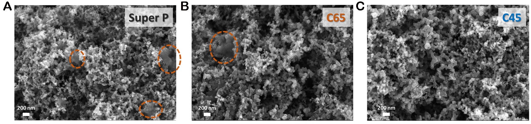
Figure 1. FESEM images of pristine electrode samples. PVDF droplets are highlighted with orange circles.
In order to better study the chemical-physical properties of the three different carbon black materials, N2 adsorption/desorption and XRD analyses were performed and are reported in Figure 2. The XRD pattern comparison of different powders is shown in Figure 2A. For all three samples, two broad diffraction peaks are distinguishable and centred at 25.3° and 43.3°, respectively. The main peak centred at 25.3°, indexed to the (002) plane, is attributable to graphite-like crystallites, while the second peak (at 43.3°) reveals the presence of graphene layers (indexed to the (101) plane)[46]. Nevertheless, due to the broadness of the peak, it can be assessed that all the samples exhibit a low graphitisation degree and a pseudo-amorphous structure. Not only does the poor stacking of graphene layers differ from the usual graphite-like structure, but it also results in a higher interlayer distance. Indeed, the displacement between reflection sites, denoted as d in Bragg’s law (see Supplementary Note 1), was found to be equal to 0.352 ± 0.003 nm for all three samples. The bigger distance with respect to the common graphite value (i.e., 0.335 nm) is beneficial for the reversible insertion of the wider K-ions, preventing electrode pulverisation[47]. Figure 2 also shows N2 adsorption/desorption isothermal curves (panel b) and the cumulative pore volume (panel c). All three samples show a similar pore size distribution, with a huge amount of mesopores and a negligible amount of micropores. Adopting the IUPAC classification, all three carbon materials show high mesopores density from 2 to 20 nm and mesopores from 30 to 50 nm. According to the pore size distribution, the resulting BET-specific surface area is comparable for C65 and Super P (61.61 and 60 m2 g-1, respectively, for C65 and Super P), while it is lower for C45 (45.99 m2 g-1).

Figure 2. (A) XRD patterns; (B) N2 adsorption/desorption isothermal curves; and (C) cumulative pore volume curves of Super P (black line), C65 (red line), and C45 (blue line).
Potassium ions storage mechanism
Electrochemical measurements were performed to correlate the morphological features of the carbon black materials with their K-ion storage mechanism. In particular, CV curves allow us to better identify the voltage onsets for electrochemical reactions and the relative potential range for different storage mechanisms occurring in the cell. Namely, carbonaceous anodes are involved in three main electrochemical phenomena: (i) the SEI formation during the very initial cycles; (ii) the ion adsorption onto the electrode surface; and (iii) the insertion/extraction storage mechanism in the bulk phase. As clearly visible in Figure 3, during the first CV cycle, a broad reduction peak from 1.2/1.0 to 0.45 V indicates the first phase of SEI formation. This indexing is also confirmed by the work carried out by Wu et al. and Li et al. on potassium-based systems working with the same electrolyte[48,49]. Furthermore, it is interesting to notice from Figure 3 that the area ascribed to the irreversible reactions is greater for Super P compared to C65, but what is even more unique is how negligible the SEI formation peak is in the C45-related current-potential graph. As a matter of fact, calculating and subtracting the areas under the CV curves of the 1st and 2nd cycle per each material results that Super P, C65, and C45 systems lost - in this potential range - 28%, 25%, and 6% of their initial capacity, respectively. Moving our focus on the previously mentioned two storage mechanisms, all three carbon materials exhibited, from the 2nd CV cycle, two broad cathodic peaks: the first one, from 0.01 to 0.45 V, mainly described the diffusion and insertion of K-ions, while the second one, comprised between 0.45 and 1.2 V, referred to all the surface-driven reactions. Since the redox potential of the K+/K couple is very close to that of Li+/Li (i.e., -2.93 V vs. SHE and -3.04 V vs. SHE, respectively), similar potential ranges are expected for the electrochemical reactions. As a matter of fact, in previous works, the Li-ion intercalation into the confined space of the pseudo-graphitic system was scanned between 0.01 and 0.3 V

Figure 3. CV traces at the constant scan rate of 0.1 mV s-1 for six cycles for (A) Super P, (B) C65, and (C) C45 electrodes. Dashed green lines separate two voltage ranges (i.e., from 0.01 to 0.45 V and from 0.45 to 1.2 V), where SEI formation starts occurring and the ion insertion is more prominent.
Moving forward to the anodic scan, differences in the depotassiation mechanism arise. C65 [Figure 3B] worked mainly on a single oxidation peak centred at around 0.6 V, the intensity of which diminished through scanning cycles; a less visible peak in the lower potential region started increasing from the 2nd cycle. The same behaviour was observed for the C45 cell, excluding the peak around 0.25 V, which is more prominent. The two oxidative peaks approximately between 0 and 0.45 V and between 0.45 and 0.75 V may refer to the ion bulk deintercalation and the surface ion release, respectively. This assignment of the potential windows to the two depotassiation mechanisms will also be confirmed - in the forthcoming sections - through the results of Dunn’s method. The dynamic profile of C65 and C45 can be translated as the formation through the cycles of a more stable and conductive SEI layer, which created - at the same time - preferential pathways for the accommodation of K-ions in graphite interlayer space. This was witnessed by the arising of the related peak within 0-0.45 V, ascribed to the deintercalation. On the other hand, in the Super P profile, the oxidative pair became a single wide peak comprising both the depotassiation behaviours. Concerning the SEI layer, according to the work made by Xu et al., the binder choice determines the starting potential value of the electrolyte reductions and the products, which will constitute the SEI layer[51]. The poor electrochemical stability of PVDF, together with its stronger interaction with the EC solvent, causes the triggering of the decomposition reactions at higher potential values, acting as a catalyst for the electrolyte decomposition and, thus, causing a higher irreversible capacity amount in the upper voltage range. As also suggested from the magnitude of the CV area ascribed to irreversible capacity, galvanostatic cycling results of the three carbon electrodes confirmed that the capacity lost in the upper voltage region (from 1.2 to 0.45 V) was notably higher in the PVDF-based systems. As a matter of fact, the discharge capacity loss during the galvanostatic cycling in the 1st cycle in the upper voltage region represented only 10% of the total C45 system loss, while 22% and 29% of the total irreversible capacity were calculated for C65 and Super P samples, respectively.
The voltage vs. specific discharge capacity profiles from the galvanostatic cycling performance at 0.05 A g-1 in Figure 4 and Supplementary Figure 1 are in accordance with the concepts detailed above since - in the first cathodic polarisation - surface dominated reactions (e.g., SEI formation) started at 1.2 V for all three systems, while more extreme SEI formation was witnessed by a very large plateau starting around 0.8 V for Super P; a similar but shorter plateau was observed for C65, while no plateau at all occurred for C45. The latter observation confirmed that 10% of the total capacity was lost by the C45 sample during the first voltage region. A second plateau started at 0.3 V for all the voltage profiles, pointing at the K-ion intercalation between the graphene layers. The presence of a small slope for these curves (instead of a perfect plateau) was indicative of a very slow insertion process. From the second cycle, two different tilts were present: a near-slope from 1.2 to 0.45 V was ascribed to the presence also of surface-driven storage contribution, and a more horizontal trend below 0.45 V corroborated the dominance of K-ion insertion. The disappearance of the first plateau and its replacement by the near-slope (1.2-0.45 V) in the voltage profiles of C65 and Super P from the 2nd cycle validated the theory, according to which most of the surface reactions of the first cycle are ascribed to irreversible reactions. The differential capacity analysis, as shown in Figure 5, clearly confirmed the occurrence of an electrolyte reduction on the pristine electrode (starting from 1.2 V) only for the PVDF-based electrode. Indeed, in Figure 5C, most of the irreversible capacity is actually ascribed to the low potential region. As a matter of proof, the shaded area in Figure 4C is meant to visually confirm that the CMC-based system lost irreversible capacity mainly through thermodynamically accelerated side reactions in the low voltage region, while in Figure 4A and B, it emerges that irreversible reactions occurred throughout all the potential window for Super P and C65 samples.
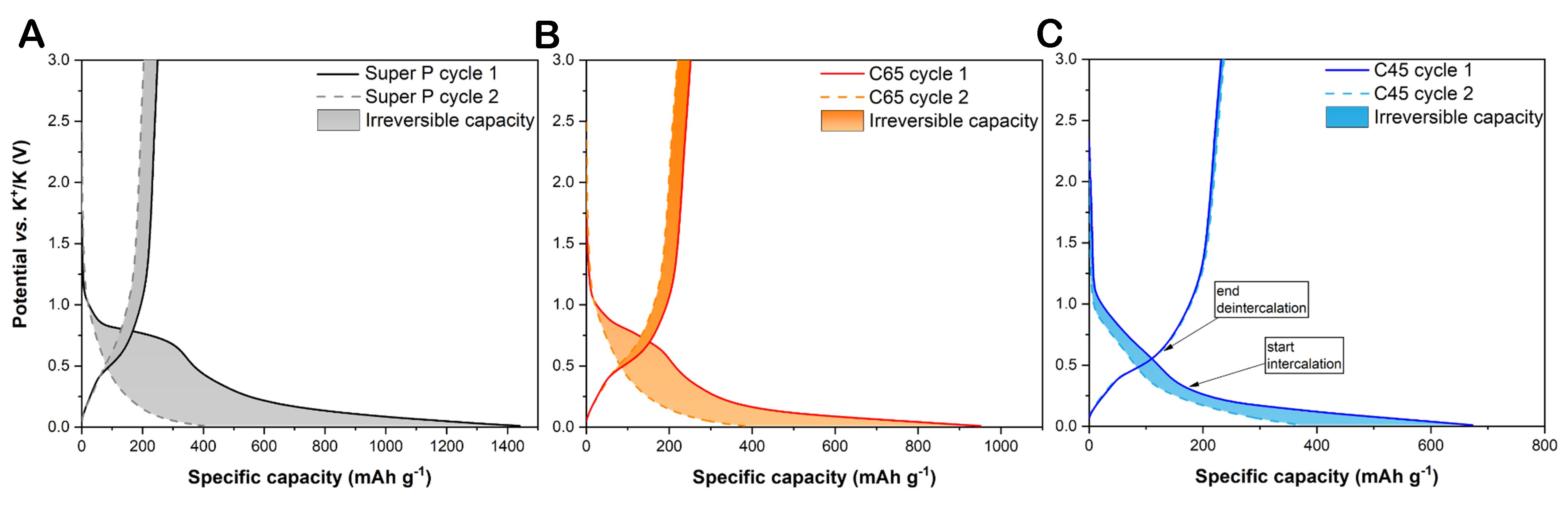
Figure 4. Voltage profile of charge and discharge steps at the first and second cycle at 0.05 A g-1 for (A) Super P, (B) C65, and (C) C45 electrodes. The filled areas are meant to better visualise the potential profile changes and represent the lost charge and discharge energies between the first and second cycles.
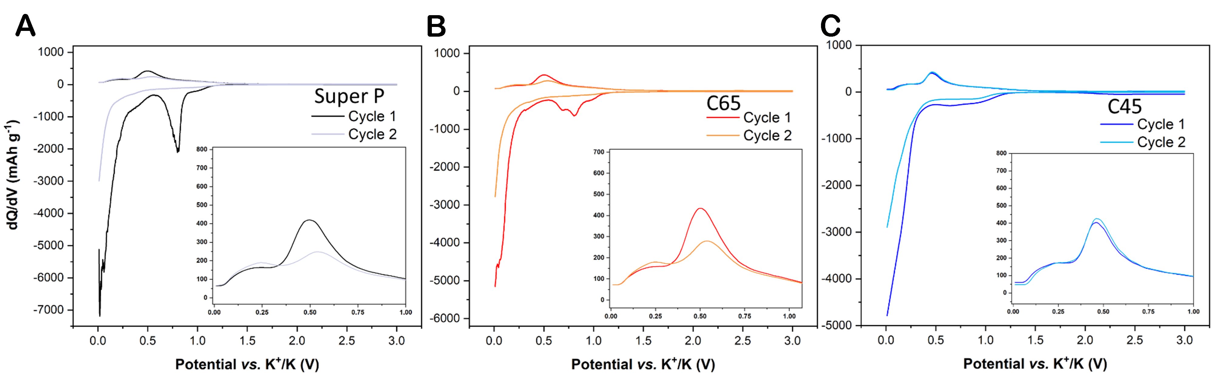
Figure 5. Differential capacity analysis of the potassiation and depotassiation of the first two cycles for (A) Super P, (B) C65, and (C) C45 electrodes.
Our evidence of the surface-driven storage mechanism has led us to stress that the spread of pseudo-amorphous and nanoparticulate electrodes calls to consider the concept of pseudocapacitive materials. Indeed, there are two different kinds of storage mechanisms that can occur in the electrode material: (i) Faradaic (electron-transfer) processes or (ii) ion accumulations at the electrical double layer. The two mechanisms can be differentiated by observing their cyclic voltammograms and galvanostatic voltage profiles. The capacitor response (accumulation of ion) will give linear potential dependency with time during galvanostatic charge/discharge, along with rectangular CV traces. Battery-like materials, instead, will display their Faradaic processes through plateaus and intense peaks in voltage profiles and voltammograms, respectively. The divergence from both abovementioned behaviours comes from a pseudocapacitive material response. In this latter, the charge storage is entirely Faradaic as in all battery-like materials, but they will mainly store charges through redox reactions on their surface instead of the inner regions, sharing similar electrochemical responses to capacitors. In this regard, CVs and potential profiles of the materials analysed in this work are the litmus test of pseudocapacitive behaviour[52]. Indeed, given their pseudocapacitive responses (i.e., near-sloped potential profiles and symmetrical broad redox peaks in CV traces), further electrochemical analyses are worthy of being carried out.
A useful way to try getting insights into these “in-between” (promiscuous) materials is to analyse their current responses in CV at increasing scan rates (i.e., by VSCV) according to Dunn’s and Trasatti’s methods. Inspired by Cottrell’s equation[52], Dunn and Trasatti stated that the current response at the voltage variation in CV is proportional to the square root of the voltage scan rate in diffusion-controlled processes, while the capacitive current response results proportional to the scan rate. For those materials with behaviour being indistinguishable among capacitor-like or battery-like, a current response that is the sum of the capacitive and the diffusion currents is considered:
Relevant consideration can already be drawn from the VSCV spectra shown in Figure 6: for all three carbon-based materials, the increase of the scan rate provokes the current response increase, but the presence of diffusion-controlled storage mechanism induces the escalating current peak shift, too. Based on the previous considerations, it can be inferred that both capacitive and diffusion-controlled capacities are involved. However, Trasatti’s and Dunn’s methods are indispensable for differentiating and quantifying the presence and entity of each of them. Trasatti’s method results suggested that Super P owned the highest amount of pseudocapacitive capacity (i.e., 65.5% of the total), followed by C45 (63%) and C65 (56%). Notably, in Figure 6, C65 shows the widest peak shift, while for Super P, it is the narrowest; therefore, it should not be surprising that they showed the highest and the lowest presence of diffusive currents, respectively. On the other hand, Dunn’s method - applied on the CV carried out under a 0.2 mV s-1 scan rate - matches similar percentages [Figure 7], but it also identifies the voltage range in which the diffusion or charge accumulation is occurring. The capacitive contributions represented by the filled areas in Figure 7 confirm that the charge capacity values provided between 0.01 and 0.5 V are almost entirely ascribed to diffusion-controlled deintercalation. Meanwhile, from 0.5 to 3 V, only surface-driven reversible reactions contribute to the charge capacity. Regarding the discharging process, once the SEI layer has formed during the previous five activation CV cycles, almost exclusively K-ion insertion occurred from 1.5 to 0.9 V; from 0.9 V, the surface-driven reaction increased up to dominate at 0.5 V; instead, from 0.5 V down to 0.01 V, both of the two mechanisms occurred in equal amounts. It is also worth noticing that since diffusion-controlled storage is a kinetic-dependent process, as it is influenced by the applied scan rate, it is also determined by the applied current. As a matter of fact, Supplementary Figure 2 shows that the peak shift of the differential capacity curves at increasing specific currents of the rate performance confirms the potential range of the diffusion-driven storage again. Here, the arrows in the insets are meant to trace the intercalation peak centre shift from 1 to 0.5 V and the deintercalation peak from 0.25 to 0.6 V.
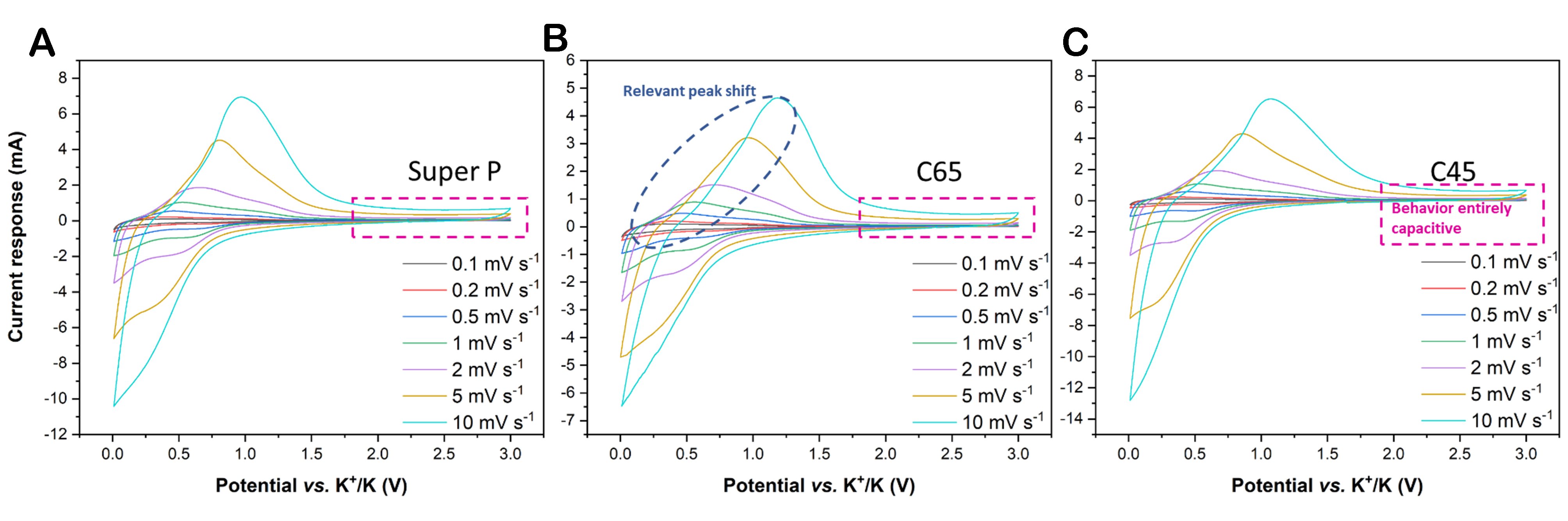
Figure 6. VSCV traces for (A) Super P, (B) C65, and (C) C45. The visible current shift in C65, due to diffusion-controlled storage processes, is encircled in blue, while the perfect rectangular CV shape related to the capacitive behaviour is framed in magenta.

Figure 7. Dunn’s method applied to the CV collected at 0.2 mV s-1 for (A) Super P, (B) C65, and (C) C45. Separation of capacitive and diffusive contributions is highlighted by the filled areas.
To further validate the proposed voltage assignment to the diffusive and deposition mechanisms, the total current derived from Eq. 1 is hereby described by the following empirical equation (and by its logarithmic form):
Let v represent the voltage scan rate, with a and b as adjustable parameters. A capacitor will have the b parameter equal to 1, indicating the occurrence of surface-driven processes only, while in battery-like electrodes, diffusion-controlled currents will lead to a b value of 0.5. Electrode materials with b values comprised between 0.5 and 1 electrochemically behave neither totally capacitive nor battery-like. As shown in Figure 8, the b values, calculated for different voltages of the reduction branch, depict a behaviour that varies among the explored potential windows, describing the succession of reduction reactions occurring on the outer and the inner surfaces: the decrease of the b values starting from 1.2 V denotes the occurrence of diffusion-driven reductions, reaching the higher dominance at 0.8 V, where all these three carbon-based electrodes show b values of 0.5-0.55. Moving from this minimum value, the occurrence of surface-driven processes increases the b value up to its maximum at 0.3 V, where the capacitive current represents more than half of the total current. At 0.3 V, the C45 system reached the highest b value of 0.9, as confirmed by Dunn’s profile, where at around 0.3 V, the area under the cathodic curve is completely filled in blue [Figure 7C]. Moreover, the graph shows a further decrease during the final intercalation process through the inner region between 0.3 and 0.01 V. Instead, the b value for the C45 electrode at 0.01 V is still high, in accordance with Dunn’s results.

Figure 8. Cathodic b values obtained for the three carbon black materials.
The two diverse storage mechanisms can also be detected through their effect on the ion diffusion through the electrode thickness when the potential changes. The difficulty that an ion faces crossing interfaces and diffusing along intricate pathways can be quantified by the diffusion coefficient (DC), calculated as follows:
where τ is the time interval of the charge or discharge pulses, mact is the net electrode active mass, S is the geometric area of the electrode, Mc is the molar mass of the carbon black, and Vc is its molar volume[49,53]. Their ratio
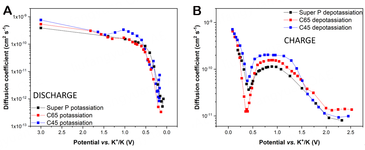
Figure 9. Diffusion coefficient at different voltage values in the (A) discharge and (B) charge steps.
These varied storage kinetics, also influenced by the electrolyte and binder choice, resulted in different electrochemical responses. Figure 10 shows the current rate (panel a) and long-cycling (panel b) performances of the three investigated systems. The irreversibility trends displayed by CV traces and differential capacity curves are confirmed by the capacity loss of the three carbon electrodes during the first cycles of their rate performance profile [Figure 10D]. As a matter of fact, Super P lost - during the first discharge of the rate performance - 806 mAh g-1, which is almost twice the values of C65 and C45 (i.e., 460 and 300 mAh g-1, respectively). Sharing a similar mass loading among all three electrodes, both rate performance and the long-cycling profiles overall show higher specific capacity values for the C45 system, together with a better capacity retention ability. Indeed, after 500 cycles of the long cycling performances, the C45 system retained 64% of the discharge capacity provided at the 10th cycle, compared with 57% and 56% of C65 and Super P, respectively. Furthermore, it is also vital to consider how much of the K-ions adsorbed and intercalated during the discharge were reversibly recovered during the charge: this is expressed by the Coulombic efficiency (CE) values shown in Figure 10C, where the better reversibility of the ion shuttling process in C45 is easily noticeable. The graph suggests that, during the very first cycles, the CMC-based system reached better reversibility of the potassiation/depotassiation mechanism; yet, after
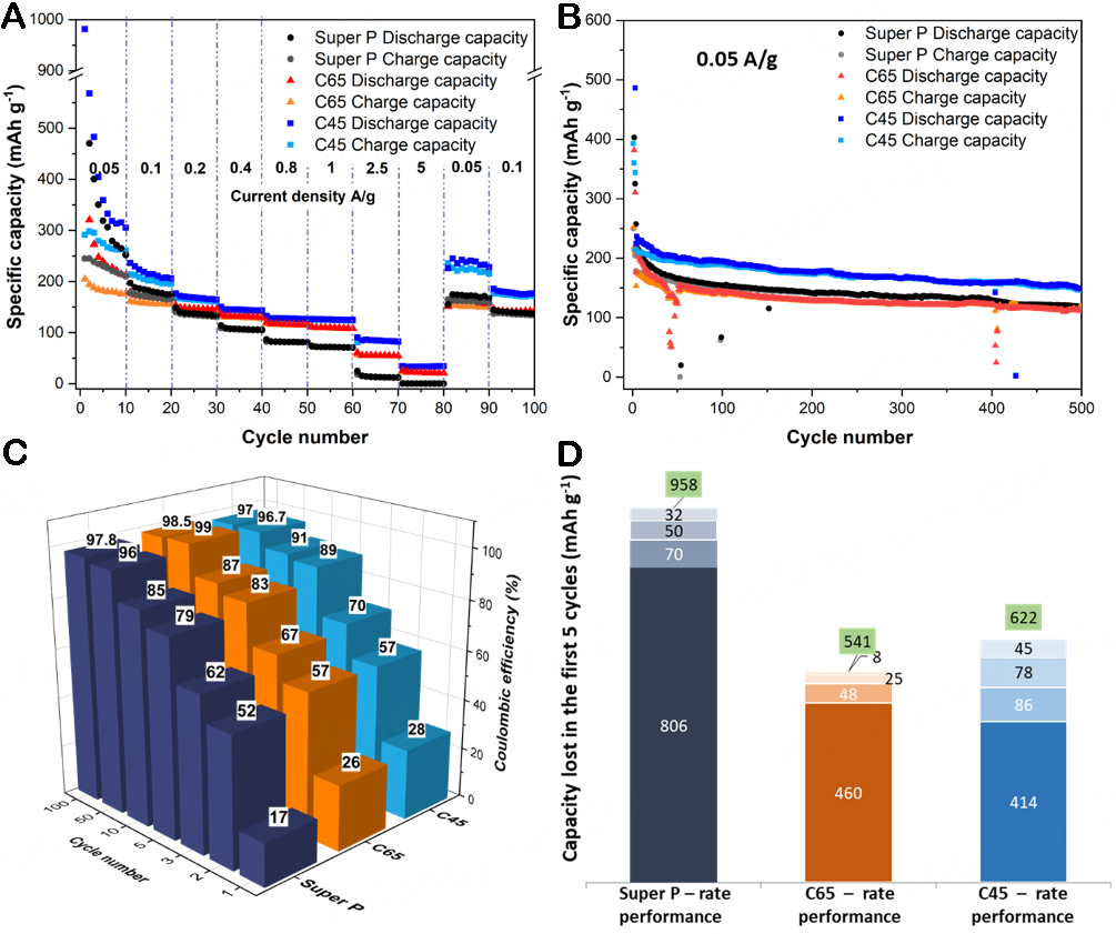
Figure 10. (A) Rate performances, (B) long cycling performances, and (C) Coulombic efficiency values during the long cycling test for half-cells assembled with the three different carbon-based materials. (D) Cumulated irreversible capacity (in mAh g-1) lost by the three systems during the first five cycles of the rate performance test. Each bar (with its reported value) represents the capacity lost between one cycle and the subsequent. The entire stack with the value in green displays the total capacity lost after five cycles.
As a concluding remark of this electrochemical section, it must be stated that - besides the different chemical nature of the three investigated carbon-based electrodes - the binder also plays a reasonable role in affecting the performance and stability of the cells. In this article, CMC has been used with C45, while PVDF has been chosen for C65 and Super P systems; this choice is motivated by state-of-art protocols adopted by the scientific community, where the best electrode fabrication processes have already been optimised considering the best compatibility among active material, binder, and solvents. Therefore, we have not explored C45:PVDF, C65:CMC, and Super P:CMC systems since they would not have resulted in uniform electrodes, leading to unreliable and non-reproducible electrochemical performance.
SEI layer characterisation
Reversible redox reactions are not the only processes occurring within the anode and cathode potential window. As known, indeed, irreversible side reactions lead to the formation of the so-called SEI layer, a passivation film made of decomposition reaction precipitates, which is responsible for the irreversible capacity, decrease of mass transport of the electrolyte liquid phase, and increase of the electrolyte resistance detected during the initial cycles. Nevertheless, this passivation layer has the potential to even boost the electrochemical performances of the storage system, acting as a protective blanket on the electrode that, thanks to its mechanical flexibility, prevents further electrolyte decomposition and possible active material exfoliation and pulverisation. The SEI layer is made of products coming from unavoidable reduction reactions of the solvent and anions constituting the electrolyte; thus, its morphology, composition, and electrochemical features are determined by the chosen electrolyte solution. Low molecular weight organic solvents are the most used; in particular, ethylene carbonate (EC) provides high polarity and high dielectric constant, promoting salt dissolution; however, given its high viscosity and high melting point, it is thinned with a low viscosity solvent, which promotes the ion mobility, such as diethylene carbonate (DEC). As regards the salt, KPF6 is probably the most widely used compound for PIB electrolytes, featuring a well-balanced mix of electrochemical responses. A homogeneous, stable, and flexible SEI layer with negligible electronic conduction and low diffusion of the liquid phase, but high selectivity and permeability of K-ions can actually improve the cell performances and lifespan. The achievement of this result depends on the SEI layer composition, which is made by organic and inorganic products.
From the literature on LIBs[55-59], the formation of a double-layered SEI structure has been widely proved. This structure consists of an inner dense layer comprising insoluble and stable inorganic compounds and an outer part, which is mainly organic, soluble, and metastable. Presumably, the inorganic products of the system investigated in this study will be K2CO3, KF, K2O, and phosphorous oxides (-POx); meanwhile, a bigger range of organic compounds are possibly found, such as oligomers [e.g., poly(ethylene oxide) (PEO)-like] and potassium alkyl alkoxides and carbonates (ROK and ROCO2K, where R is a low molecular weight alkyl group). XPS techniques were adopted to study the three electrodes before and after ten galvanostatic cycles at 0.05 A g-1 to shed light on the chemical composition of the SEI layers and relative differences among them, also correlating half-cells electrochemical performances to SEI layer structures and elemental composition (see Supplementary Note 2). Starting from the analysis performed on the bare carbon electrodes before being tested, we can infer the differences in the C1s peak (see Figure 11A) among them, especially related to the region between 286 and 290 eV, where most of the carbon- and oxygen-related bonds are located. When we deconvoluted the three curves, we obtained the data shown in Table 1 and Figure 11A. It can be noted that Super P was the one with the lowest amount of C-OH bonds, while the C45 sample was that with the highest C=O bond content[60]. The more ordered carbonaceous structure belonged to the C65 electrode, which showed a sharper peak in the C-C component (at 284.8 eV), with a low full width at a half maximum (FWHM) value (equal to 0.92 eV). The increase in the FWHM value (equal to

Figure 11. XPS C1s and K2p HR regions for as-prepared electrodes (A) and tested electrodes (B).
XPS HR deconvolution data obtained for Super P, C65, and C45 samples. Relative atomic concentrations % of C, O, F, and K elements are given in Supplementary Table 1
| Super P | C65 | C45 | |
| C1s region | |||
| Before cycling | |||
| C-C/H | 61.6 | 57.7 | 55.8 |
| C-OH | 21.9 | 25.5 | 24.6 |
| C=O | 5.3 | 6.4 | 13.7 |
| O-C=O/COOH | 8.5 | 8.0 | 2.4 |
| π-π* | 2.7 | 2.4 | 3.5 |
| Post cycling | |||
| C-C/H | 27.5 | 27.9 | 12.7 |
| C-OH | 33.1 | 42.4 | 55.8 |
| C=O | 13.5 | 5.5 | 15.2 |
| -(CO3)2- | 25.8 | 24.2 | 16.2 |
| K2p region | |||
| Post cycling | |||
| K2CO3 | 70.1 | 55.4 | 50.0 |
| KF | 23.9 | 42.9 | 49.6 |
| KPF6 | 6.0 | 1.6 | 0.4 |
Starting from C1s and K2p HR regions of tested electrodes [Figure 11B], which overlap each other, we can see that there are differences both in carbon- and potassium-related peaks. If we want to delve into more details and correlate our deconvoluted data with SEI layer composition, we have to check for “fingerprint” chemical shifts that can be assigned to specific molecules or compounds. In particular, if we want to consider the inorganic phases, we have to look at the K2p, P2p, and F1s regions
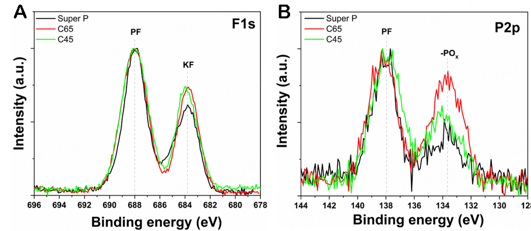
Figure 12. XPS HR spectra for tested electrodes, highlighting (A) F1s and (B) P2p regions. Intensity has been normalised in each graph to better compare signals.
For the purpose of pushing the investigation of the SEI layer structure, it is necessary to understand the reaction chain occurring within the electrochemical system. The EC is the first component that starts decomposing, namely at 1.2 V in PVDF-based systems or at 1 V in CMC-based ones (see CV traces in Figure 3), having the lowest unoccupied molecular orbital higher than that of KPF6 and precipitating together with K-ions on the electrode surface as K2CO3, constituting the inner inorganic layer[51,59,61]. The higher reduction potential for the EC decomposition with respect to the theoretical one (i.e., 0.9 V) is ascribable to the pseudo-amorphous and disordered structure of the carbonaceous electrode, which offers different electric fields and, thus, covers a broader range of decomposition potentials. Additionally, the aforementioned PVDF-K+-EC chemical affinity increases the EC reduction activity in PVDF-based systems up to 1.2 V. The K+-coordinated EC molecules can undergo a two-electron reduction reaction that provides intermediate radical [EC]- anions, which are further decomposed to precipitate mainly as K2CO3 and potassium ethylene dicarbonate [PEDC, (CH2OCO2K)2] but also as (CH2CH2OCO2K)2 or
To draw some final insights from the XPS analysis, it can be said that the very first cathodic polarisation of C65 and Super P samples experienced a relevant number of irreversible reactions, as inferred from dQ/dV curves [Figure 5], which - according to our suppositions - are mainly related to the one and two-electron reduction processes of the [EC]- anions, which produce a high number of potassium alkyl carbonates that can diffuse back in the electrolyte or decompose again as K2CO3. As a matter of fact, PEDC presence is higher in Super P and C45 samples, but, at the same time, there is a higher amount of produced K2CO3 in Super P (70.1%) with respect to C65 (55.4%) and C45 (50.0%) (see Table 1). Thus, it can be speculated that C65 had produced a relevant amount of PEDC during the first cathodic reduction through the voltage window from 0.9 to 0.5 V, but at lower potentials most of this potassium alkyl carbonate has been decomposed into K2CO3. Instead, for the Super P system, the yield of organic compounds is so high that, even after secondary decompositions, this system holds the highest quantity of both PEDC and K2CO3. As regards the C45 sample, given its different chemical nature, potassium alkyl carbonates have been produced mainly at potentials lower than 0.5 V and lately decomposed into K2CO3 up to a quantity similar to that observed for C65. Furthermore, as suggested by the absence of residual KPF6 salt on the C45 sample, more KF and PF5 are formed, leading to further KF and relevant presence of PEO. Finally, considering the beneficial presence of the ion-conducting and electron-blocking K2CO3 for both C65 and C45 samples, as well as the increasing production of the effectively passivating KF from C65 (42.9%) to C45 (49.6%), the superior electrochemical rate performance of C65 and C45 is well substantiated. Instead, the presence of PEO, which is ion-conducting and can act as a binder for the heterogeneous organic and inorganic blended SEI layer, ensures both a higher diffusion coefficient and a flexible and elastic protective SEI layer for the C45 system. The decrease of the interfacial resistance ascribed to the conductive SEI layer is also witnessed by the decrease of the semicircle diameter upon charge/discharge cycles; this occurs for all three electrodes, the Nyquist plots of which are shown in Supplementary Figure 5.
Relative atomic concentrations of C, O, F, and K elements are given in Supplementary Table 1.
FESEM images [Figure 13] of the surfaces of the three samples (relative to samples which underwent ten galvanostatic cycles at 0.05 A g-1) further corroborate the XPS results. C45 and C65 maintained a disordered and flexible structure, similar to the pristine one (see Figure 1), with a uniform passivation layer. Instead, Super P resulted in a very different structure, more embedded, and with most of the empty volumes filled by decomposition products. This thick and non-homogeneous SEI layer justified the severe initial capacity loss, as well as poor diffusion coefficient and rate performance, but also confirmed the significant presence of the conductive K2CO3, which allows a proper specific capacity, at least for lower current rates.
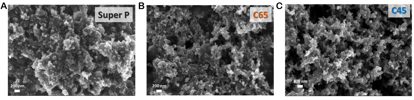
Figure 13. FESEM images of the three carbon materials taken after ten galvanostatic cycles at 0.05 A g-1.
CONCLUSIONS
The addition of conductive materials to the electrode slurry tips the balance in favour of a working and performing electrode. Even when the conductive additive is needed in minimal part (i.e., 3 wt%), but above all, when it is asked to be the conductive skeleton of the electrode (i.e., 40 wt% for organic electrodes), the electrochemical response is influenced by the carbon additive choice. Far from looking for the “best” conductive additive, this work was aimed at tracing the electrochemical behaviour of carbon black species in PIBs. To this purpose, it was found that Super P-based systems experienced the highest loss of irreversible capacity during the first discharge (i.e., 806 mAh g-1 with respect to 460 and 300 mAh g-1 for C65 and C45, respectively). As foreseen by CV and dQ/dV curves, this capacity loss occurred mainly in the upper voltage region (i.e., between 1.2 and 0.45 V vs. K+/K) and mainly for Super P and C65 systems, which lost 29% and 22%, respectively, of the total irreversible capacity of the first cycle, vs. only 10% for C45. This is due to their distinct electrostatic charge, surface functionalities, and binder choice, which determine different decomposition reactions and, thus, SEI layer composition. Indeed, the presence of the PVDF binder in C65 and Super P electrodes determined a higher voltage onset for the EC decomposition, causing a higher irreversible capacity in the upper voltage region for these two systems. In this potential region, a lot of organic compounds were produced. As evidenced by the XPS analysis, while in the C65 system they further decomposed into the conductive and passivating K2CO3 and KF, in the Super P system the SEI layer composition was dominated by organic and metastable compounds. On the contrary, C45-based cells (using CMC as a binder) showed a SEI layer composition with the highest presence of inorganic compounds; it also contained organic PEO, which is ionically conductive and can act as a flexible binder for the SEI layer. All these observations resulted in impressive current rate performances for C65 and C45 cells, with respect to the very poor one detected for Super P.
As a final consideration, for those studies adopting a relevant amount of carbon black as a conductive additive, it is poorly scientific not to consider their influence on the electrochemical profiles. Indeed, in this paper, thanks to Dunn’s and Trasatti’s methods, we highlighted the pseudocapacitive mechanism of the pseudo-amorphous carbon black materials commonly employed in LIB and PIB fields, indicating a decreasing presence of diffusion-controlled storage from Super P to C65, which is fundamental to consider when looking at CV peaks and profiles slopes.
Even if this work assessed the feasibility of these carbon materials as anodic substrates for PIBs, it also provided the tools to distinguish the influence of carbon additives on the electrochemical profiles. Nonetheless, it also enlightened that totally pseudo-amorphous and high surface area carbon black species are adequate and more performant in PIBs with respect to graphitic-like carbons, and this aspect will guide the formulation of electrodic materials within the scientific community.
DECLARATIONS
Acknowledgements
Prof. Armandi M is gratefully acknowledged for the support provided for the calculation of the BET-specific surface area. Dr. Versaci D acknowledges support from FSE REACT-EU - PON Ricerca e Innovazione 2014-2020 program (Ministerial Decree no. 1062/2021).
Authors’ contributions
Conceived and designed the analysis: Trano S, Bella F
Collected the data: Trano S, Castellino M, Fontana M
Contributed data/analysis tools: Versaci D, Fagiolari L, Francia C
Performed the analysis: Trano S, Castellino M, Fontana M
Wrote the paper: Trano S, Bella F
Availability of data and materials
Data is available upon request to the corresponding author with a motivated reason.
Financial support and sponsorship
None.
Conflicts of interest
All authors declared that there are no conflicts of interest.
Ethical approval and consent to participate
Not applicable.
Consent for publication
Not applicable.
Copyright
© The Author(s) 2024.
Supplementary Materials
REFERENCES
1. Shyu C. Lessons from the World Bank’s solar home system-based rural electrification projects (2000-2020): policy implications for meeting Sustainable Development Goal 7 by 2030. Energy Rep 2023;9:2820-38.
2. Ren Z, Li H, Yan W, et al. Comprehensive evaluation on production and recycling of lithium-ion batteries: a critical review. Renew Sustain Energy Rev 2023;185:113585.
3. Tan KM, Yong JY, Ramachandaramurthy VK, Mansor M, Teh J, Guerrero JM. Factors influencing global transportation electrification: comparative analysis of electric and internal combustion engine vehicles. Renew Sustain Energy Rev 2023;184:113582.
4. Hassini M, Redondo-iglesias E, Venet P. Lithium-ion battery data: from production to prediction. Batteries 2023;9:385.
5. Keppeler M, Tran H, Braunwarth W. The role of pilot lines in bridging the gap between fundamental research and industrial production for lithium-ion battery cells relevant to sustainable electromobility: a review. Energy Technol 2021;9:2100132.
6. Mu T, Wang Z, Yao N, et al. Technological penetration and carbon-neutral evaluation of rechargeable battery systems for large-scale energy storage. J Energy Stor 2023;69:107917.
7. Abdalla AM, Abdullah MF, Dawood MK, et al. Innovative lithium-ion battery recycling: sustainable process for recovery of critical materials from lithium-ion batteries. J Energy Stor 2023;67:107551.
8. Hou J, Yang M, Zhou L, Yan X, Ke C, Zhang J. Transforming materials into practical automotive lithium-ion batteries. Adv Mater Technol 2021;6:2100152.
9. Gianola G, Speranza R, Bella F, Lamberti A. Homo-tandem-bifacial dye-sensitized solar cell: a new paradigm to boost photoconversion efficiency above limit. Solar Energy 2023;265:112116.
10. Bonomo M, Segura Zarate A, Fagiolari L, et al. Unreported resistance in charge transport limits the photoconversion efficiency of aqueous dye-sensitised solar cells: an electrochemical impedance spectroscopy study. Mater Today Sustain 2023;21:100271.
11. Masias A, Marcicki J, Paxton WA. Opportunities and challenges of lithium ion batteries in automotive applications. ACS Energy Lett 2021;6:621-30.
12. Duffner F, Kronemeyer N, Tübke J, Leker J, Winter M, Schmuch R. Post-lithium-ion battery cell production and its compatibility with lithium-ion cell production infrastructure. Nat Energy 2021;6:123-34.
13. Wang H, Chen S, Fu C, et al. Recent advances in conversion-type electrode materials for post lithium-ion batteries. ACS Mater Lett 2021;3:956-77.
14. Min X, Xiao J, Fang M, et al. Potassium-ion batteries: outlook on present and future technologies. Energy Environ Sci 2021;14:2186-243.
15. Wu X, Leonard DP, Ji X. Emerging non-aqueous potassium-ion batteries: challenges and opportunities. Chem Mater 2017;29:5031-42.
16. Pramudita JC, Sehrawat D, Goonetilleke D, Sharma N. An initial review of the status of electrode materials for potassium-ion batteries. Adv Energy Mater 2017;7:1602911.
17. Fagiolari L, Versaci D, Di Berardino F, et al. An exploratory study of MoS2 as anode material for potassium batteries. Batteries 2022;8:242.
18. Li T, Huang X, Lei S, et al. Two-dimensional nitrogen and phosphorus co-doped mesoporous carbon-graphene nanosheets anode for high-performance potassium-ion capacitor. Energy Mater 2023;3:300018.
19. Nguyen A, Verma R, Didwal PN, Park C. Challenges and design strategies for alloy-based anode materials toward high-performance future-generation potassium-ion batteries. Energy Mater 2023;3:300030.
20. Liu D, Shen J, Jian Z, Cai X. Advanced 3D-structured electrode for potassium metal anodes. Energy Mater 2023;3:300028.
21. Trano S, Corsini F, Pascuzzi G, et al. Lignin as polymer electrolyte precursor for stable and sustainable potassium batteries. ChemSusChem 2022;15:e202200294.
22. Zhang J, Zhao J. Recent advances in tin-based anode materials for potassium-ion batteries. J Energy Stor 2023;72:108366.
23. Zheng J, Hu C, Nie L, et al. Recent advances in potassium-ion batteries: from material design to electrolyte engineering. Adv Mater Technol 2023;8:2201591.
24. Xu Y, Ding T, Sun D, Ji X, Zhou X. Recent advances in electrolytes for potassium-ion batteries. Adv Funct Mater 2023;33:2211290.
25. Gandolfo M, Amici J, Fagiolari L, Francia C, Bodoardo S, Bella F. Designing photocured macromolecular matrices for stable potassium batteries. Sustain Mater Technol 2022;34:e00504.
26. Bashir T, Zhou S, Yang S, et al. Progress in 3D-MXene electrodes for lithium/sodium/potassium/magnesium/zinc/aluminum-ion batteries. Electrochem Energy Rev 2023;6:5.
27. Xiao Z, Wang X, Meng J, Wang H, Zhao Y, Mai L. Advances and perspectives on one-dimensional nanostructure electrode materials for potassium-ion batteries. Mater Today 2022;56:114-34.
28. Lin J, Chenna Krishna Reddy R, Zeng C, Lin X, Zeb A, Su C. Metal-organic frameworks and their derivatives as electrode materials for potassium ion batteries: a review. Coord Chem Rev 2021;446:214118.
29. Zhang W, Huang W, Zhang Q. Organic materials as electrodes in potassium-ion batteries. Chemistry 2021;27:6131-44.
30. Nathan MGT, Yu H, Kim GT, et al. Recent advances in layered metal-oxide cathodes for application in potassium-ion batteries. Adv Sci 2022;9:e2105882.
31. Luo G, Feng X, Qian M, et al. State-of-art progress and perspectives on alloy-type anode materials for potassium-ion batteries. Mater Chem Front 2023;7:3011-36.
32. Zhu Y, Wang Y, Wang Y, Xu T, Chang P. Research progress on carbon materials as negative electrodes in sodium- and potassium-ion batteries. Carbon Energy 2022;4:1182-213.
33. Lei H, Li J, Zhang X, et al. A review of hard carbon anode: rational design and advanced characterization in potassium ion batteries. InfoMat 2022;4:e12272.
34. Reis GSD, Petnikota S, Subramaniyam CM, et al. Sustainable biomass-derived carbon electrodes for potassium and aluminum batteries: conceptualizing the key parameters for improved performance. Nanomaterials 2023;13:765.
35. Khan N, Han G, Mazari SA. Carbon nanotubes-based anode materials for potassium ion batteries: a review. J Electroanal Chem 2022;907:116051.
36. Yuan F, Li Y, Zhang D, et al. A comprehensive review of carbon anode materials for potassium-ion batteries based on specific optimization strategies. Inorg Chem Front 2023;10:2547-73.
37. Wang J, Wang H, Zang X, Zhai D, Kang F. Recent advances in stability of carbon-based anodes for potassium-ion batteries. Batteries Supercaps 2021;4:554-70.
38. Yuan F, Zhang W, Zhang D, et al. Recent progress in electrochemical performance of carbon-based anodes for potassium-ion batteries based on first principles calculations. Nanotechnology 2021;32:472003.
39. Li W, Yang Z, Zuo J, Wang J, Li X. Emerging carbon-based flexible anodes for potassium-ion batteries: progress and opportunities. Front Chem 2022;10:1002540.
40. Lei Y, Zhang S, Dong J, et al. Potassium-enriched graphite for use as stable hybrid anodes in high-efficiency potassium batteries. Carbon 2023;201:1030-7.
41. Li W, Peng D, Huang W, et al. Adjusting coherence length of expanded graphite by self-activation and its electrochemical implication in potassium ion battery. Carbon 2023;204:315-24.
42. Qin L, Xiao N, Zheng J, Lei Y, Zhai D, Wu Y. Localized high-concentration electrolytes boost potassium storage in high-loading graphite. Adv Energy Mater 2019;9:1902618.
43. Qin L, Lei Y, Wang H, et al. Capillary encapsulation of metallic potassium in aligned carbon nanotubes for use as stable potassium metal anodes. Adv Energy Mater 2019;9:1901427.
44. Hu J, Zhong S, Yan T. Using carbon black to facilitate fast charging in lithium-ion batteries. J Power Sources 2021;508:230342.
45. Spahr ME, Goers D, Leone A, Stallone S, Grivei E. Development of carbon conductive additives for advanced lithium ion batteries. J Power Sources 2011;196:3404-13.
46. Attia PM, Das S, Harris SJ, Bazant MZ, Chueh WC. Electrochemical kinetics of SEI growth on carbon black: part I. experiments. J Electrochem Soc 2019;166:E97.
47. Larbi L, Larhrib B, Beda A, Madec L, Monconduit L, Matei Ghimbeu C. Impact of hard carbon properties on their performance in potassium-ion batteries. ACS Appl Energy Mater 2023;6:5274-89.
48. Wu Z, Zou J, Shabanian S, Golovin K, Liu J. The roles of electrolyte chemistry in hard carbon anode for potassium-ion batteries. Chem Eng J 2022;427:130972.
49. Li D, Ren X, Ai Q, et al. Facile fabrication of nitrogen-doped porous carbon as superior anode material for potassium-ion batteries. Adv Energy Mater 2018;8:1802386.
50. Wu Z, Wang L, Huang J, et al. Loofah-derived carbon as an anode material for potassium ion and lithium ion batteries. Electrochim Acta 2019;306:446-53.
51. Xu Y, Zhang C, Zhou M, et al. Highly nitrogen doped carbon nanofibers with superior rate capability and cyclability for potassium ion batteries. Nat Commun 2018;9:1720.
52. Mathis TS, Kurra N, Wang X, Pinto D, Simon P, Gogotsi Y. Energy storage data reporting in perspective - guidelines for interpreting the performance of electrochemical energy storage systems. Adv Energy Mater 2019;9:1902007.
53. Jian Z, Xing Z, Bommier C, Li Z, Ji X. Hard carbon microspheres: potassium-ion anode versus sodium-ion anode. Adv Energy Mater 2016;6:1501874.
54. Heubner C, Nickol A, Seeba J, et al. Understanding thickness and porosity effects on the electrochemical performance of
55. Andersson A, Henningson A, Siegbahn H, Jansson U, Edström K. Electrochemically lithiated graphite characterised by photoelectron spectroscopy. J Power Sources 2003;119-21:522-7.
56. Bar-tow D, Peled E, Burstein L. A study of highly oriented pyrolytic graphite as a model for the graphite anode in Li-ion batteries. J Electrochem Soc 1999;146:824.
57. Aurbach D, Cohen Y. The application of atomic force microscopy for the study of Li deposition processes. J Electrochem Soc 1996;143:3525.
58. Yan J, Xia B, Su Y, Zhou X, Zhang J, Zhang X. Phenomenologically modeling the formation and evolution of the solid electrolyte interface on the graphite electrode for lithium-ion batteries. Electrochim Acta 2008;53:7069-78.
59. Cheng XB, Zhang R, Zhao CZ, Wei F, Zhang JG, Zhang Q. A review of solid electrolyte interphases on lithium metal anode. Adv Sci 2016;3:1500213.
60. Caracciolo L, Madec L, Martinez H. XPS analysis of K-based reference compounds to allow reliable studies of solid electrolyte interphase in K-ion batteries. ACS Appl Energy Mater 2021;4:11693-9.
61. An SJ, Li J, Daniel C, Mohanty D, Nagpure S, Wood DL. The state of understanding of the lithium-ion-battery graphite solid electrolyte interphase (SEI) and its relationship to formation cycling. Carbon 2016;105:52-76.
62. Samage A, Gupta P, Halakarni MA, Nataraj SK, Sinhamahapatra A. Progress in the photoreforming of carboxylic acids for hydrogen production. Photochem 2022;2:580-605.
63. Wang H, Zhai D, Kang F. Solid electrolyte interphase (SEI) in potassium ion batteries. Energy Environ Sci 2020;13:4583-608.
64. Wagner CD, Naumkin AV, Kraut-Vass A, Allison JW, Powell CJ, Rumble JJJ. NIST standard reference database 20, version 3.4. Available from: https://srdata.nist.gov/xps/ [Last accessed on 28 Dec 2023].
Cite This Article
Export citation file: BibTeX | RIS
OAE Style
Trano S, Versaci D, Castellino M, Fontana M, Fagiolari L, Francia C, Bella F. Exploring nature-behaviour relationship of carbon black materials for potassium-ion battery electrodes. Energy Mater 2024;4:400008. http://dx.doi.org/10.20517/energymater.2023.79
AMA Style
Trano S, Versaci D, Castellino M, Fontana M, Fagiolari L, Francia C, Bella F. Exploring nature-behaviour relationship of carbon black materials for potassium-ion battery electrodes. Energy Materials. 2024; 4(1): 400008. http://dx.doi.org/10.20517/energymater.2023.79
Chicago/Turabian Style
Trano, Sabrina, Daniele Versaci, Micaela Castellino, Marco Fontana, Lucia Fagiolari, Carlotta Francia, Federico Bella. 2024. "Exploring nature-behaviour relationship of carbon black materials for potassium-ion battery electrodes" Energy Materials. 4, no.1: 400008. http://dx.doi.org/10.20517/energymater.2023.79
ACS Style
Trano, S.; Versaci D.; Castellino M.; Fontana M.; Fagiolari L.; Francia C.; Bella F. Exploring nature-behaviour relationship of carbon black materials for potassium-ion battery electrodes. Energy Mater. 2024, 4, 400008. http://dx.doi.org/10.20517/energymater.2023.79
About This Article
Special Issue
Copyright

Data & Comments
Data
0

 Cite This Article 10 clicks

 Like This Article 9
likes
Like This Article 9
likes


Comments
Comments must be written in English. Spam, offensive content, impersonation, and private information will not be permitted. If any comment is reported and identified as inappropriate content by OAE staff, the comment will be removed without notice. If you have any queries or need any help, please contact us at support@oaepublish.com.