
Quasi-solid-state electrolytes - strategy towards stabilising Li|inorganic solid electrolyte interfaces in solid-state Li metal batteries


Abstract
Solid-state batteries (SSBs) based on inorganic solid electrolytes (ISEs) are considered promising candidates for enhancing the energy density and the safety of next-generation rechargeable lithium batteries. However, their practical application is frequently hampered by the high resistance arising at the Li metal anode/ISE interface. Herein, a review of the conventional solid-state electrolytes (SSEs) the recent research on quasi-solid-state battery (QSSB) approaches to overcome the issues of the state-of-the-art SSBs is reported. The feasibility of ionic liquid (IL)-based interlayers to improve ISE/Li metal wetting and enhance charge transfer at solid electrolyte interfaces with both positive and lithium metal electrodes is presented together with a novel generation of IL-containing quasi-solid-state-electrolytes (QSSEs), offering favourable features. The opportunities and challenges of QSSE for the development of high energy and high safety quasi-solid-state lithium metal batteries (QSSLMBs) are also discussed.
Keywords
INTRODUCTION
The accelerated demand for high energy density and long cycling batteries is expediting the development of next-generation energy storage technologies. Rechargeable lithium-ion batteries (LIBs) account for a wide range of applications, such as electric vehicles, portable devices, and stationary energy storage, due to their long cycle lives, high charge-discharge rates, high specific capacity, and voltage, as well as reasonable temperature range of operation[1-3]. However, commercial LIBs are associated with limited energy density and safety-related concerns linked to poor abuse tolerance. The internal failure of a LIB is mainly caused by the intrinsic flammability of organic carbonate-based liquid electrolytes (LEs), such as ethylene carbonate (EC), dimethyl carbonate (DMC), and diethyl carbonate (DEC), volume expansion of electrodes during cycling, and uncontrollable lithium dendrite formation, affecting their broad applicability[4,5].
To achieve higher energy density, lithium metal is considered the most promising anode material due to its high theoretical capacity (3,860 mAh g-1) and low electrode potential (-3.04 V vs. standard hydrogen electrode)[6,7]. However, its use in combination with conventional LE is prevented by the thermodynamic instability of the carbonate-based organic solvent and the inability of lithium salt anion which cannot form a stable solid electrolyte interphase (SEI) on the Li surface[8]. During the charge and discharge processes, the SEI layer is partially fractured, which causes inhomogeneous Li stripping/plating and the formation of Li dendrites with small needle-shaped structures on the anode surface. These phenomena occur continuously during cycling and cause consumption of both Li metal and electrolyte, reducing the Coulombic efficiency of the batteries. In the worst case, Li dendrites grow across the electrolyte towards the cathode and cause internal short circuits which may eventually lead to fires and/or explosions[8,9].
Considering the aforementioned limitations of LIBs, solid-state Li metal batteries (SSLMBs) have been extensively studied as prospective candidates for enhancing the energy density of next-generation rechargeable batteries. A replacement of conventional LEs with solid-state electrolytes (SSEs) may offer improved performance and safety of the battery cell. SSEs can provide higher safety, acting as a physical barrier to separate negative and positive electrodes, and prevent thermal runaway phenomena under high temperatures. In addition, the excellent mechanical properties of SSEs are an advantage for the use of lithium metal as the anode material with effective suppression of Li dendrite formation[10,11].
Currently, the most common SSEs are classified into two main groups, namely solid polymer electrolytes (SPEs) and inorganic solid electrolytes (ISEs)[12]. SPEs are composed of a polymer matrix and a lithium salt which provide the lithium ions for conduction. Many polymers have been investigated, including poly(ethylene oxide) (PEO), polycarbonate (PC), poly(methylmethacrylate) (PMMA), poly(vinylidene di-fluoride) (PVDF) and poly(acrylonitrile) (PAN). Among them, PEO-based electrolytes are the most widely studied for solid-state batteries due to their good electrochemical stability with Li anode and excellent compatibility with Li salts[13,14]. SPEs offer advantages over ISE, such as good processability and outstanding flexibility, but their applicability is limited by low ionic conductivity at room temperature and poor anodic electrochemical stability[15].
ISEs, which can be divided into three main groups, oxide-, phosphate- and sulphide-based electrolytes, exhibit high ionic conductivity (> 0.1 mScm-1 at room temperature) and excellent thermal stability (thermal runaway temperature when in contact with Li >300 °C)[16]. Some ISEs also offer high electrochemical stability (> 4.0 V as measured by linear sweep voltammetry and also supported by DFT calculation[17]). Several types of ISEs have been studied, including Li superionic conductors (LISICONs), Na superionic conductors (NASICONs), garnets, and perovskites as oxide/phosphate-based ISEs and thio-LISICON,
Although practical applications of ISEs are still limited by numerous concerns including high cost, difficult manufacturing, and high interfacial charge transfer resistances arising from rough contact with the electrodes[19-21], ISEs are considered the most promising materials to replace the current LEs. For practical applications, the SSEs must satisfy several prerequisites, namely (i) high ionic conductivity, more than
Recently, a new concept was proposed for the design of novel SSEs with improved safety, durability, and electrochemical performance, involving the addition of a small amount of liquid material (usually a LE) to ISEs, yielding quasi-solid-state electrolytes (QSSEs). The resulting composites based on LE and ISEs retain the solid-state nature, i.e., no fluidity, self-standing, and no liquid leakage, which are different from liquid or gel-type electrolytes. In such systems, ISEs function as a separator while at the same time granting ionic conductivity, whereas LEs solve the problems of poor Li-ISE contact and sluggish interfacial kinetics, which cause the decline of SSLMB performances. In this context, ionic liquids (ILs) have attracted significant attention in addition to conventional LE for the development of QSSEs because of their remarkable properties, such as thermal and chemical stability, wide electrochemical stability window (ESW) up to 5 or
In the past decades, ILs have been studied as a potential electrolyte additive in advanced electrochemical devices. For instance, in polymer-IL composite electrolytes, i.e., organic-organic system, the incorporation of IL in polymers as plasticisers and as ion sources results in fast ion conduction and improved electrochemical, thermal, and interfacial properties[29-32]. This is also demonstrated in an organic-inorganic hybrid system, whereby ILs are combined with either Li+ conductive filler (i.e., ISE) or non-conductive inorganic fillers (the former is of interest and summarised in Section “Ionic liquid electrolyte (ILE)-containing QSSEs”). As one example of the latter combination, Ito et al. investigated silica nanoparticle composites with 75 vol% IL-Li salt, which exhibited desirable ion conductivity (> 10-4 S cm-1 at room temperature) and reported a quasi-solid-state lithium metal battery (QSSLMB), Li|QSSE|LiCoO2, exhibiting high capacity of 126 mAh g-1[33]. Wen et al. reported a QSSE based on a biomimetic leaf-like Al2O3 and ILs. This system promoted the migration of Li+ both in bulk and at the interface, improving the interfacial stability and restraining Li dendrite formation during long-term cycling. Symmetric Li cells assembled with this QSSE exhibited a long cycle lifetime of 1,100 h at a high constant current density of 0.5 mA cm-2[34].
As battery development transitions from liquids to solids, the LE or IL additives in QSSEs can also be combined with polymers to ensure the safety property of the overall QSSLMBs and the mechanical stability of ISEs. In the development of battery electrolytes, incorporation of a small amount of inorganic fillers in the polymer matrix has already been demonstrated, the combination of which reduces the crystallinity of polymers, i.e., inorganic filler serves as a “solid plasticiser”[35]. Ternary composites, an inorganic filler, polymer, and LE or IL, have also been reported[36]. In contrast to these filler-in-polymer systems, there is a new trend in the development of polymer-in-ISE composites designed to improve both the electrochemical and mechanical properties of ISEs. Since the ISE is the main component that governs the ion conduction along with ILs, the strategy for material design should differ from the well-developed filler-in-polymer systems, and this is summarised in Section “Polymer-liquid-inorganic QSSEs”.
Prior to the discussion on the development of QSSEs, we present an overview of ISEs along with the chemical-electrochemical and mechanical properties which control dendritic Li formation in SSLMBs. Principally, we discuss the new emerging classes of QSSEs based on ISEs with a focus on the Li/electrolyte interface and interphase. Attention is also devoted to the mechanism of dendritic Li formation in SSLMBs. Lastly, the discussion is expanded to different types of QSSEs containing a IL, ILs and hybrid systems based on SPE-IL-SSE as an outlook for the development of novel SSEs with reliable safety and high performance.
OVERVIEW OF INORGANIC SOLID-STATE ELECTROLYTES
The history of ISEs dates back to 1,838[18], when Faraday discovered that Ag2S and PbF2 become good ion conductors when in their heated states (e.g., ~1 S cm-1 at 400 °C for PbF2). It was a century later that early SSBs based on silver salts, such as Ag/AgI/I2, were reported, but their performance was poor, including low voltage (< 1 V) and low discharge current[37]. In the same period, fast Li+ conduction in inorganic solid materials, such as LiI and Li3N, was discovered[38-40]. Then, the 1960s marked an important turning point when the fast 2D Na+ ion transport in β-alumina (Na2O•11Al2O3) was discovered, leading to the birth of the term “solid-state ionics”. Its use in high-temperature sodium-sulphur batteries has allowed for the proliferation of practical applications of ISEs in energy storage systems. The first LIBs with ISEs were reported in the 1990s, employing lithium phosphorous oxynitride (LiPON). The research on this topic has flourished since then and accelerated the study of solid-state LIBs and led to the development of other types of materials, as summarised below.
The historical development of ISEs is reported in Figure 1[41], together with their performances[18,42].

Figure 1. (A) Historical development of solid-state electrolytes. Reprinted (adapted) with permission from Wang et al.[41]. Copyright (2020) American Chemical Society. (B) Radar plots showing the performance properties of sulphides and oxides. This figure is quoted with permission from Manthiram et al.[18]. (C) Comparison of ionic conductivity of various solid-state lithium-ion conducting electrolytes. This figure is quoted with permission from Goodenough et al.[42].
Garnet: Garnet-type Li ion conductors have A3B3(XO4)3 as the general chemical formula (A = Mg, Ca, Y, La or rare earth; B = Fe, Al, Ge, Ga, Ni, Mn or V; X = Ge, Si, Al), containing three different types of cation sites, in which A, B, and C are eight, six, and four oxygen coordinated respectively[43]. Thangadurai et al., developed a family of garnet oxides Li5La3M2O12 (M = Nb, Ta), among which Li5La3Ta2O12 exhibited the highest chemical and electrochemical stabilities and a Li-ionic conductivity of 1 × 10⁻⁶ S cm-1 at room temperature[44]. To improve the ionic conductivity of these compounds, Li-rich garnet-type, such as
Perovskite: Materials of this family have the general ABO3 formula, consisting of BO6 octahedra structure with A-site cations placed at the corner of the unit cell. Their most appealing feature is structural flexibility arising from versatile doping agents for A-site and/or B-site[54]. The most representative and promising Li-conductive perovskite structure is Li3xLa2/3-xy1/3-2xTiO3 (LLTO)[55]. Inaguma et al. reported the first LLTO, specifically Li3xLa2/3-xTiO3, with high bulk-ionic conductivity (10-3 Scm-1), but the total ionic conductivity, including grain boundary conductivity, was only 2 × 10⁻⁵ S cm-1[56]. Compared to garnet-type ISEs, these perovskite compounds show superior chemical and thermal stability in air over a wide temperature range. Additionally, LLTO-type ISEs exhibit wide ESW; thus, they can be combined with high-voltage cathode materials[57]. In contrast, LLTO is unstable in direct contact with Li, which arises from the Ti4+ reduction and results in unexpected electronic conductivity[58].
LISICON: First described by Hong[59] in 1978, LISICON [Li14Zn(GeO4)4] is the typical representative of this family of ISEs. This material offers high ionic conductivity at elevated temperatures (1.25 × 10⁻¹ Scm-1 at
LiPON: Lithium phosphorus oxynitrides (LiPON) first received significant attention in the 1970s as SE for the development of thin-film solid-state macro batteries[63]. LiPONs are commonly prepared via sputtering of Li3PO4 in N2 plasma, resulting in amorphous, glassy thin films with compositions of LixPOyNz
NASICON: NASICON refers to a sodium super ion conductor with the chemical formula of NaM2(PO4)3, where M can be a transition metal (Zr[73], Ge[74,75], Ti[76]). In 1976 Goodenough and Hong et al. identified the first ISE Na1-xZr2SixP3-xO12 (0 ≤ x ≤3) with a rhombohedral crystal structure and a space group of R-3c. In the range of 1.8 ≤ x ≤ 2.2, the structure undergoes a small distortion to monoclinic symmetry with space group C2/c at ambient temperature[42]. NASICON-type Li-ion ISE, LiM2(PO4)3, can be prepared by replacing Na-ion with Li-ion. However, the ionic conductivities of LiTi2(PO4)3 and LiGe2(PO4)3 materials are lower than that of the Na-ion analogues. To address this issue, a partial substitution of Ti and Ge with d-block elements was investigated to promote Li ion migration[77]. One of the most successful dopants is aluminium (Al) which allows the presence of more lithium ions in the crystal structure, resulting in enhanced Li ion conductivity. ISEs with compositions of Li1+xAlxTi2x(PO4)3 (LATP) and Li1+xAlxGe2x(PO4)3 (LAGP) show room temperature ionic conductivity around 10-3 Scm-1[78,79].
Sulphide electrolytes: To improve the low room-temperature ionic conductivity of LISICON-type oxide ISEs, a new class of materials was developed by the substitution of O2- with S2- in the framework (thio-LISICON). Kamaya et al. developed Li10GeP2S12 (LGPS) with an ionic conductivity of 1.2 × 10⁻² S cm-1 at room temperature, i.e., comparable to that of organic LEs[80]. These SSEs are attracting increased interest owing to their high Li-ion conductivity resulting from the larger size of S2-, which broadens ion conduction pathways in the electrolyte structure, and the higher polarisability of S2-, which weakens the attraction between lithium and sulphide ions. Several first principles modelling studies were carried out to interpret the high ionic conductivity obtained for these compounds. These results suggested that the most energetically favoured LGPS is a 3D superionic conductor with a tetragonal unit cell of PS4 and GeS4 and space group P42/nmc. In this structure, Li-ion diffusion can occur along the two-dimensional diagonal direction in the ab plane, with activation energies reduced to 0.30 eV and along the c-axis with activation energies of 0.19 eV, both of which guarantee the superionic conductivity of LGPS[81,82]. Motivated by the cost of Ge, there are strategies to replace Ge with Si and Sn or alternatively to form the LGPS phase exclusively based on Li-P-S (specifically, Li9.6P3S12)[83].
Other types of sulphide-based fast ion conductors are glass-ceramics electrolytes, among which the binary system (100-x)Li2S-xP2S5 (70 < x < 80) is of particular interest because of its low cost, high ionic conductivity (10-3-10-4 Scm-1) and wide ESW to Li+/Li[84]. Additionally, glass-ceramic sulphides exhibit good plasticity to compensate for volumetric changes of Li metal and provide better stability towards the Li electrode compared to crystalline electrolytes, in which grain boundaries facilitate dendrite formation and growth[85]. An effective method to yield high lithium-ion conductivity is based on the addition of lithium iodide (LiI) in the Li2S-P2S5 electrolyte. In particular, enhanced mechanical stability and an optimised composition of the SEI layer are achieved at the interface between the Li and the LiI-modified electrolyte, also preventing the growth of Li dendrites[86,87].
Lithium argyrodites (Li6PS5X with X = Cl, Br, or I) are also known as fast lithium-ion conductors with a similar structure to Cu- and Ag-argyrodite compounds, which is based on tetrahedral close packing of anions with cubic unit cell and F
Despite the advantageous features of sulphide-based ISEs, one of the main concerns with sulphide-containing SEs is their poor chemical stability when they are accidentally exposed to atmospheric moisture. All these materials undergo hydrolysis with moisture forming H2S gas, leading to material degradation. These sulphide-type electrolytes are not stable and also against the reduction of Li metal, increasing the interfacial resistance, because insulating products such as Li3P, Li2S, LiX, and Li15Ge4 can be formed[92]. Moreover, recent reports revealed that these electrolytes are unstable when in contact with delithiated, high-voltage oxide cathode materials[93].
Li METAL SOLID ELECTROLYTE INTERFACE
Despite the significant advances of ISEs in terms of intrinsic ionic conductivity, designing Li/ISE interfaces with favourable properties remains challenging. The term interfacial is defined as a combination of several physical and chemical processes that occur at the Li/electrolyte interface during cycling, which define the compatibility between the Li electrode and the SE, as well as the physical and mechanical stability of the interface contact. These processes include SEI formation, Li structural and volumetric changes, formation of Li-depleted space-charge layers, and Li dendrite growth[94]. These complex processes affect and limit the overall performance of SSBs.
The chemical-electrochemical process
To explain the fundamental interface reactions and mechanisms of SSBs, the open-circuit energy diagram of a typical Li|SSE|LixMyO2 SSLMB was proposed based on the band theory [Figure 2A][95].
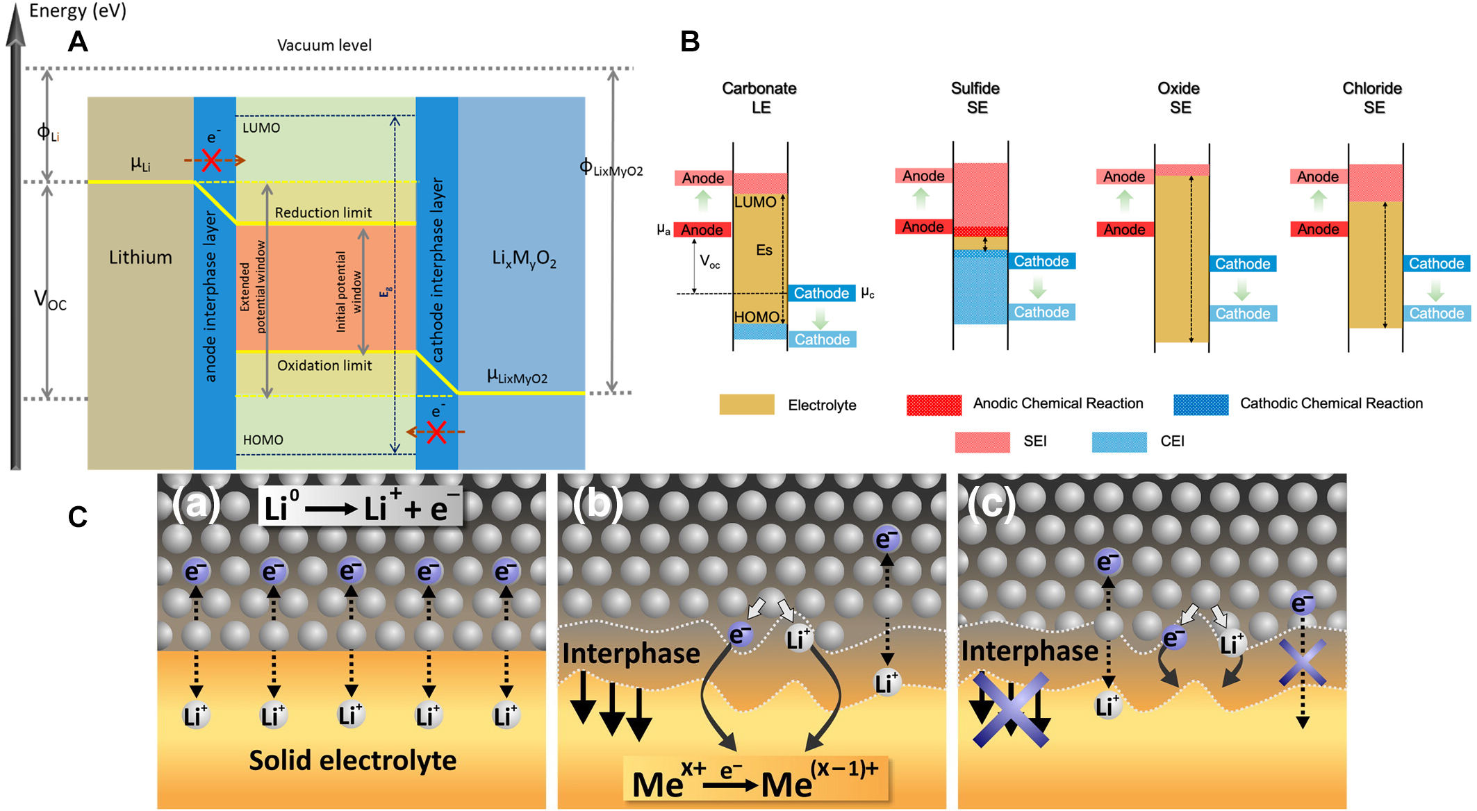
Figure 2. (A) Schematic open-circuit energy diagram for a Li|SSE|LixMyO2 battery system where μLi and μLixMyO2 represent the chemical potentials of Li and the cathode materials, respectively. Reprinted (adapted) with permission from Pervez et al.[95]. Copyright (2019) American Chemical Society. (B) Schematic band diagrams of the HOMO and LUMO of different classes of electrolytes. Reprinted (adapted) with permission from Banerjee et al.[97]. Copyright (2020) American Chemical Society. (C) The interphase formed between SSE and lithium metal with (a) thermodynamically stable two-dimensional interphase, (b) mixed ionic-electronic conducting interphase (MCI) formed due to thermodynamic instability of SSE with lithium, and (c) growth of stable three-dimensional interphase due to the poor electronic conductive reaction products. This figure is reproduced with permission from Wenzel et al.[98].
The ESW of an SSE can be determined, in a first approximation, by the energy separation (Eg) between the lowest unoccupied molecular orbital (LUMO, conducting band) and the highest occupied molecular orbital (HOMO, valence band) of the electrolyte. Although this simple concept is being challenged, it may be useful for the preliminary screening[96-98].
The open circuit voltage (VOC) of the Li|SSE|LixMyO2 cell can be calculated by the following equation:
where μLi and μLixMyO2 are the chemical potentials of Li and LixMyO2, respectively.
In an ideal scenario, the interface is thermodynamically stable when the chemical potential of the electrode materials (μLi and μLixMyO2) is within the ESW of the electrolyte; in other words, within the HOMO-LUMO range. In Figure 2B, the schematic HOMO and LUMO band diagram for various classes of electrolytes is reported. If an electrode and the SSE have a mismatch in chemical potential, i.e., μLi > LUMO or μLixMyO2 < HOMO, spontaneous chemical reactions can occur once these two materials are put in contact, resulting in the formation of an interphase between the electrolyte and the electrodes (the SEI forms at the anode or cathode electrolyte interphase (CEI) at the cathode)[97].
Based on the intrinsic properties of different kinds of SSEs, three different electrode/electrolyte interphases can be identified in SSLMB [Figure 2C]. In the same figure, the first interphase (a), being the ideal case, is thermodynamically stable, i.e., no electrolyte decomposition or chemical side reactions take place. In the second type (b), the formed interphase is a mixed electronic and ionic conductor, known as “a mixed conductive interphase” (MCI), resulting in the continuous degradation of the SSE because electrons can reach it. Eventually, the process leads to cell failure because SSE and/or Li are consumed in this parasitic reaction, which in the worst case, causes internal cell short circuits. The third type (c) is the case when the interphase is electronically insulating, thus obstructing the SSE decomposition. However, the interphase provides Li ion conductivity allowing cell operation[98].
Zhu et al. reported first-principle calculations to investigate the chemical and electrochemical stabilities of the Li|SSE interfaces. Their calculations demonstrated that most SSEs have a limited ESW. Sulphide-based ISEs have significantly narrower ESW than the oxide-based ones, being reduced already below 1.6 V vs.
Ma et al. demonstrated that two reactions: the reduction of LLZO surface upon contact with lithium metal and the simultaneous Li+ ion diffusion into the ISE, maintain the charge balance, leading to the formation of a stable and ultrathin (6 nm) tetragonal-like LLZO interphase, which prevents further interfacial reactions without affecting the bulk ionic conductivity of LLZO [Figure 3A][104]. The presence of dopant species in the lattice of LZZO, improving Li+ conductivity, has a key role in controlling interfacial reactivity, thus affecting the stability of LLZO in contact with Li metal. Zhu et al. reported a study on Ta, Nb, and Al-doped LLZO samples demonstrating the formation of oxygen-deficient interphase (ODI) due to the reduction of Zr4+. The formation of an extensive ODI layer on Al-doped LLZO (due to a significant Zr4+ reduction) stabilises the ISE in contact with Li, resulting in a low interfacial impedance. In contrast, Nb-doped LLZO, exhibiting slightly less Zr4+ reduction, showed the highest interfacial impedance with Li, which increased consistently with time due to the propagation of the reaction into the bulk[105].
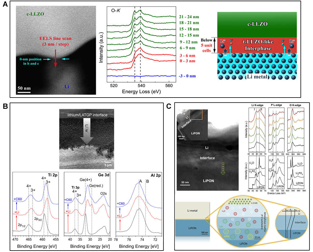
Figure 3. (A) Atomic-resolution high-angle annular dark-field-scanning transmission electron microscope image of cubic-LLZO
Hartmann et al. observed the coupled diffusion of lithium ions and electrons into the bulk of a commercial ISE containing Ge, Ti, and Si (LATGP) by means of SEM and XPS. When a thin lithium film (~200 nm thickness) was formed on the SSE via vacuum deposition, the interface undergoes changes, accompanied by an increase in interfacial resistance, due to the diffusion of lithium ions and electrons into the bulk of the SSEs, confirming the formation of an unwanted MCI between ISE and lithium metal anode [Figure 3B][106]. In the MCI region, Ge and Ti were found in reduced oxidation states.
Similarly, for both perovskite-type LLTO and NASICON-type LATP, their high reactivity towards lithium metal anodes is mainly due to the reduction of Ti4+ to Ti3+ at potentials below 1.7-1.8 V vs. Li+/Li. Therefore, Ti-containing ISE undergoes degradation reactions leading to an increase in the Li|ISE interfacial resistance over time[107].
Unlike other SSEs forming MCI, LiPON are known to exhibit good electrochemical stability with many electrode materials due to the formation of a stable SEI with Li. Structural characterisations of the interphase by means of XPS display that such an SEI is composed of Li3PO4, Li2O, and Li3N mixture, in which Li2O mostly contributes to low electronic conductivity whereas Li3N offers the highest Li-ion conductivity [Figure 3C]. The formed thin and compact interphase can protect LiPON from further decomposition with Li[68,108].
Physical-mechanical processes
Apart from the chemical-electrochemical stability issues, undesirable physical-mechanical interactions at the Li|ISE interface also affect the performance of SSLMBs. Poor physical contact at Li|ISE solid-solid interface results from a poor wetting phenomenon of the ISE by Li, which can be evaluated by simple contact angle measurements between ISEs and molten Li[109]. Many oxide-based ISEs present a lithiophobic property due to their high interfacial energy against Li, which leads to large contact angles (> 90°), reducing the effective Li-ion transfer area between ISEs and Li. As prepared, lithium garnet electrolytes exhibit a rough surface and high contact angle (ca. 146°), i.e., poor wetting, with Li. This results in inhomogeneous current distribution and high Li|ISE interface resistance, leading to high cell polarisation. As demonstrated by Sharafi et al., it is due to the presence of contaminants such as Li2CO3, and LiOH formed on the LLZO surface after exposure to ambient air, inducing poor Li wettability and high interfacial resistance
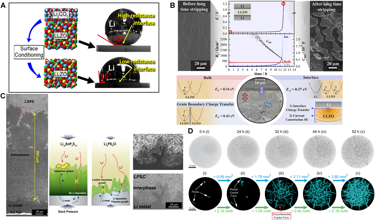
Figure 4. (A) Contact angle measurements of molten metallic Li on LLZO before and after surface cleaning. Reprinted (adapted) with permission from Sharafi et al.[110]. Copyright (2017) American Chemical Society. (B) Morphology of the Li metal anode side facing the LLZO before assembling the cell and after long-time stripping. The potential profile and the extracted impedance contributions showed a complete contact loss after around 12 h of stripping and a deposited lithium layer thickness. Schematic summary of the activation energies measured with temperature-dependent impedance spectroscopy. The interface charge transfer and current constriction phenomena in LLZO close to the interface are affected by the contact geometry, as shown in the sketch on the bottom right. Reprinted (adapted) with permission from Krauskopf et al.[111]. Copyright (2019) American Chemical Society. (C) Cross-sectional SEM image of the cathodic Li electrode and LSPS (on the left) and LPSC (on the right). Schematic illustration showing the overall reactions occurring in the interphase of Li with LSPS or LPSC. Reprinted (adapted) with permission from Lee et al.[114]. Copyright (2021) American Chemical Society. (D) 2D slices from the centre of the LAGP pellet before electrochemical cycling and after cycling for 24, 32, 44, and 52 h. The gradual formation of 3D crack networks was confirmed throughout the entire LAGP pellet upon cycling. Reprinted (adapted) with permission from Tippens et al.[115]. Copyright (2019) American Chemical Society.
Even in the absence of contamination layers, the charge transfer at the Li|ISE interface can be hindered by the mechanical processes that take place at the interface. Krauskopf et al. reported important insights on the chemo-mechanics of the Li|LLZO interface, demonstrating that at low applied pressures, charge transfer and constriction resistances are responsible for the high interfacial resistances[111]. Constriction resistances, also denoted as spreading resistances, are electrical contact resistances that occur because of incomplete surface contact between electrical conductors and the resulting current line bundling at the small contact spots. Thus, negligible interfacial resistances can be obtained by applying high external pressure of about 400 MPa. In addition, they observed a key process that takes place at the Li|LLZO interface under anodic operating conditions. As explained by the following Kroger-Vink-notation:
When a lithium ion passes through the interface from Li to LLZO, it leaves an electron e′(Li) and a vacant site
The sulphide-based ISEs, owing to their amorphous nature, can form close contact with electrode particles simply by pressing at ambient temperature and can provide good mechanical contact, both resulting in low resistances at the electrode|ISE interface. However, several studies have shown a loss of contact between active materials and sulphide-based ISEs due to mechanical fractures formed during cycling. Recently,
Similarly, Tippens et al. demonstrated that using X-ray tomography, the chemo-mechanical degradation of a Li|Li1+xAlxGe2-x(PO4)3(LAGPO) interface caused by the progressive interphase volume increase during electrochemical cycling, resulting in the propagation of cracks within the bulk of the ISE [Figure 4D][115]. The crack propagation inside the ISEs, caused by the Li-plating stress, is of great significance in understanding the failure of SSLMBs[116]. To make these processes more intelligible, Xu et al. built an electro-chemo-mechanical model for the crack propagation in LAGP induced by the stress from the electrochemical plating of Li. They found that the geometry, number, and size of Li filaments, in addition to the size of pre-existing voids in an ISE usually formed during sintering, are the main factors directing the degradation processes in SE. Damage related to the crack formation is found to preferentially occur in the region of the SE/Li interface with great structural fluctuations. Moreover, a large number density of Li filaments promotes the propagation of damage and cracks in SSEs. Therefore, the reduction of the porosity of ISE represents an interesting approach to suppressing its degradation[117].
These findings evidence a direct correlation between the interfacial mechanical properties and the battery performance, suggesting that the formation of a thin interphase offering pure ionic transport, together with good mechanical properties, is necessary to stabilise the Li|ISE interface.
Li DENDRITE GROWTH IN INORGANIC SOLID ELECTROLYTES
The primary concern at the Li|ISE interface is the formation of Li dendrites, which causes several detrimental effects, such as loss of interfacial contact, crack formation in ISEs, and formation of internal short-circuit[118]. Metallic lithium is a plastic and ductile metal with a Young’s modulus of 1.9-7.98 GPa and a yield strength ranging from 0.41-2 MPa. According to the Monroe and Newman model, developed for SPEs, Li dendrite growth can be successfully suppressed when SSEs possess Young’s modulus over two times higher than that of Li metal[119]. From this early model, it was expected that ISEs would be able to prevent Li-dendrite growth because of their great robustness and high Young’s modulus. However, it was recently demonstrated that Li dendrites penetrate into stiff ISEs on cycling, even under limited current densities[120,121]. The Monroe-Newman model fails because it assumes both lithium and SE as pure elastic materials, with the latter being free of defects and chemically stable against Li. In contrast, porosity and pre-existing local inhomogeneous defects such as cracks, grain boundaries and void, are inevitable in ISEs, and these defects play a key role in the propagation of Li dendrites. In fact, Porz et al. conducted a study on amorphous Li2S-P2S5, polycrystalline β-Li3PS4, LLZO (specifically Li6La3ZrTaO12), and single crystalline LLZO to understand the mechanism of Li dendrite growth. They confirmed that lithium dendrites grow and propagate through the defects, pores, and cracks in crystalline materials, whereas no occurrence of dendrites was observed solely in amorphous Li2S-P2S5[122].
Shen et al. investigated the deposition of Li into the pores and cracks of LLZO processed at different temperatures (1,050, 1,100, and 1,150 °C) using synchrotron X-ray tomography. As the sintering temperature was increased from 1,050 to 1,150 °C, the porosity of LLZO decreased while the connectivity between the porous region increased. They demonstrated that the interconnected pores facilitated lithium transport along with undesirable dendrite growth within these microstructures, causing short circuits at lower critical current densities (CCD). On the contrary, samples with disconnected pores showed higher CCDs, indicating that, with regards to shorting, all microstructural features such as grain boundaries, pores character, and density contribute to battery failure [Figure 5A][123]. Cheng et al. showed the occurrence of Li dendrite propagation along Al-doped LLZO grain boundaries, which resulted in short-circuiting of
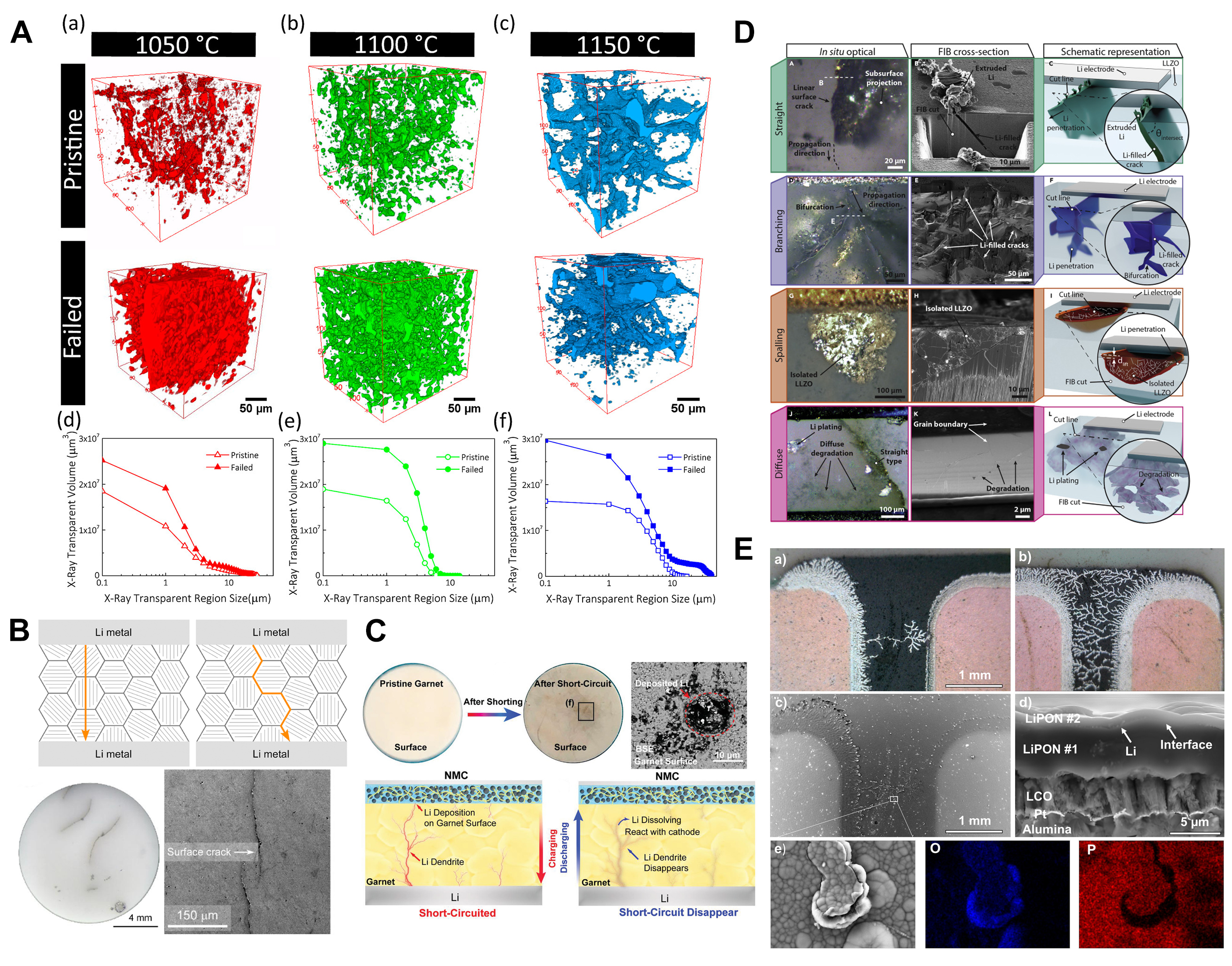
Figure 5. (A) X-ray tomographic reconstructions of voids within LLZO samples sintered at (a) 1,050, (b) 1,100, and (c) 1,150 °C. The changes in pore size distribution between the pristine and failed electrolytes are shown in (d-f) for 1,050, 1,100, and 1,150 °C. Reprinted (adapted) with permission from Shen et al.[123]. Copyright (2018) American Chemical Society. (B) Illustration of trans-granular and inter-granular Li metal plating through polycrystalline LLZO and optical and SEM images of a cycled LLZO pellet showing the appearance of black linear features caused by the propagation of metallic Li. This figure is quoted with permission from Cheng et al.[124]. (C) Photographs of garnet pellets before and after shorting. After shorting, the garnet surface facing the NMC cathode becomes yellow with numerous black lines and spots. The dark spots reveal potential Li dendrites on the cycled garnet pellet. In the backscattered electron (BSE) SEM image of the garnet surface facing the cathode after cycling, the dark area is likely the deposited Li. Scheme of the reversible short-circuit in the garnet-based full cell, in which the short-circuit happens in the charging stage but disappears in the discharging stage. This figure is quoted with permission from Ping et al.[127]. (D) Optical image of Li penetration with different types or morphologies, and SEM images together with the schematic illustration of straight type, branching type, spalling type, and diffuse type Li-penetration. This figure is quoted with permission from Kazyak et al.[130]. (E) (a and b) Optical micrographs of Cu current collectors and associated Li tree structures. (c) BSE SEM image of the area, shown in the first optical images and (d) cross-sectional BSE SEM image of the battery. (e) Zoomed-in BSE SEM image with associated Energy Dispersive Spectroscopy (EDX) analysis of the end of one of the tree structures. This figure is quoted with permission from Westover et al.[131].
To address the issue related to the pre-existing pore, Zheng et al. evaluated the addition of lithium-rich additive Li6Zr2O7 (LZO) in garnet Ta-doped LLZO (Li6.5La3Zr1.5Ta0.5O12) to obtain high-density sintered LLZO. During the sintering process, LZO is decomposed into Li2O and Li2ZrO3, which have two fundamental functions: Li2O compensates Li-loss that occurs during the sintering, whereas Li2ZrO3 fills up the voids between the grains, both enhancing the intergranular bonding and successfully improving the dendrite-resisting ability of the ISE[125].
Han et al. investigated the formation of dendrites in SEs by monitoring the dynamic evolution of Li concentration profiles within LLZO, amorphous Li3PS4 and LiPON during Li plating. Among the three ISEs, no apparent changes in the Li concentration profile were detected in LiPON, while the deposition of Li within LLZO and Li3PS4 was observed. The origin of this phenomenon is considered to be correlated with the higher electronic conductivity of LLZO and LPS (10-9-10-7 Scm-1) than LiPON (10-15-10-12 Scm-1) promoting the intergranular formation of Li dendrites[126]. In addition, it was confirmed by Ping et al. that in LLZO-based full cells, a Li-rich phase formed in the garnet ISE when charged, forming an electrically conductive pathway. During discharge or resting of the cells, the formed Li-rich phase was consumed by chemical reactions with the cathode or the local garnet matrix, resulting in a partial or complete short-circuit. [Figure 5C][127]. Furthermore, Biao et al. discovered that the presence of a high concentration of
The quality of the Li|SE interface/interphase plays an important role in Li dendrite growth, i.e., the CCD value above which Li penetration occurs. In LLZO, surface cleaning and/or the use of interfacial layers allow the reduction of the interfacial impedance enabling current densities up to 1-2 mAcm-2 at room temperature[129]. Kazyak et al. studied the Li|Al-doped LLZO, combining operando optical and post-mortem electron microscopy. They recognised four distinct morphologies of Li filaments (straight, spalling, branching, and diffuse) in the LLZO structure [Figure 5D] when the cell is cycled above CCD. The fourth morphology, however, was not observed in any of the optimised cells offering low Li interfacial impedance. Moreover, the Li within these structures can be reversibly cycled, but at high current densities, the Li filaments propagate via a mechanical crack-opening mechanism, of which the rate increases with increasing current density. Similar Li dendritic growth was also observed in glassy LPS[130].
LiPON is considered a prospective ISE that can prevent the penetration of Li from the anode to the cathode due to its homogeneity (no grain boundaries nor porous structure arising from the radio frequency magnetron sputtering). Westover et al. artificially synthesised a LiPON|LiPON interface and demonstrated that Li can deposit at such an interface [Figure 5E], but is confined to a 2D layer, confirming the ability of LiPON to block Li dendritic growth[131].
Overall, Li dendrites formation in SSLMBs is driven by inhomogeneity at the Li|ISE interface resulting from non-uniform interphase and the intrinsic porous microstructure of ISEs, especially oxide-based ones. The standing challenges, including chemical and mechanical stability, high ionic/electronic conductivity ratio, good contact with Li metal and low charge transfer impedance over many plating/stripping cycles, are yet to be resolved, requiring further design and engineering efforts.
QUASI-SOLID-STATE ELECTROLYTES
Quasi-solid-state electrolytes (QSSEs) can be considered as an intermediate state material between LE and ISEs, providing a good compromise in ionic conductivity, interfacial properties, and mechanical stability. Generally, they are expected to be an efficient strategy towards the improvement of the above-mentioned challenges of SSBs, such as (i) chemical and electrochemical stability; (ii) optimal Li|ISE interface and interphase, and to a lesser extent; and (iii) safety.
Liquid electrolyte-containing QSSEs
The addition of a minimum amount of LE at the electrode|SSE interface or into SSE pores can provide chemical building blocks enabling the formation of a stable interphase. Additionally, the LE may provide paths for Li ion transport hence ensuring a chemically and physically stable Li|electrolyte interface[132].
Despite the presence of the liquid component, QSSEs are expected to be safer than conventional LEs because of the lower amount of flammable liquid, which is additionally confined in the SE pores and/or at the interface. Overall, cells employing QSSEs are expected to overcome the poor performances of both LE- and ISE-based batteries [Figure 6A][133].

Figure 6. (A) Radar chart of the LIBs based on different electrolytes. conventional organic electrolytes, all-solid-state electrolytes, and quasi-solid-state electrolytes This figure is quoted with permission from Lv et al.[133]. (B) Ion transport across the phase boundary between a LE and an ISE showcasing the transport of ions across the phase boundary and the SLEI are dominant factors for the overall impedance (upper) and working principle of the 4P set-up for electrochemical impedance spectroscopy (EIS) measurements on the LE|SSE|LE cell (bottom). This figure is quoted with permission from Busche et al.[135]. (C) SEM images of (a) as-synthesized LLZT and (b) LLZT after being soaked in LE. Capacity and efficiency values of Li|LLZTO|LiFePO4 cell, employing hybrid electrolyte with n-BuLi at different current densities and room temperature. EIS results of the Li|LiFePO4 cell without (bottom, on the left) and (bottom, on the right) with n-BuLi before and after the cycling tests. Reprinted (adapted) with permission from Xu et al.[137]. Copyright (2017) American Chemical Society. (D) Illustration of lithium ion and electron fluxes inside the conventional cathode. (Top), comparison of electrochemical impedance spectra of the symmetric cell with a structure of Li|GC-LATP|Li and Li|LE|GC-LATP|LE|Li. The volume of LE is 2 µL. Charge and discharge curves and rate performance of Li|LiFePO4 employing GC LATP/LE hybrid electrolytes. This figure is quoted with permission from Wang et al.[139].
However, the two components must be chemically stable on contact; thus, the chosen combination of liquid and ISE is critical. With respect to lithium sulphur batteries, Judez et al. reported on the following suitable combinations: LATP-type with 1 M LiClO4-EC/DMC, 1 M LiPF6-EC/DMC/DEC or EC/DME,
With respect to the QSSE based on LAGP and LiTFSI in DOL/DME, Wang et al. demonstrated that the QSSE suppresses the polysulphide shuttling effect and improves the interface contact between the electrolyte and Li. From XPS and energy dispersive spectrometer (EDS)/SEM measurements, it was demonstrated that no side reaction between Li and polysulphides occurred. As a result, discharge specific capacities of 1,528 mAh g-1, 1,386 mAh g-1 and 1,341 mAh g-1 were achieved at C/20, C/5 and C/2 rates, respectively, with good Coulombic efficiency[136].
Based on several preliminary studies, it was considered that the phenomenon of co-decomposition occurred in all QSSEs, and the properties of the SLEI would be dependent on the electrolyte combinations. Despite the added resistance, various studies demonstrated significant enhancement in the interfacial properties due to the addition of LE.
Xu et al. studied the QSSE consisting of Ta-doped LLZO (Li7La3Zr1.5Ta0.5O12), displaying a Li+ ion conductivity of 6 × 10⁻⁴ S cm-1 at room temperature, and a carbonate-based LE containing butyl lithium (n-BuLi), a superbase. This QSSE was employed in Li|LiFePO4 batteries displaying superior electrochemical performance by virtue of a lower interfacial resistance resulting from the addition of a small amount of
Wang et al. reported the impressive electrochemical performance of the Li|LiFePO4 cell employing the QSSE composed of a glass ceramic, Li1.4Al0.4Ti1.6(PO4)3 (GC-LATP), coated with a small amount (2 μL) of LiPF6 in EC/DMC/DEC 1:1:1 in vol. The QSSLMB delivered a specific capacity of 125 mAh g-1 at 1C and
Since QSSE is able to physically separate the anode and cathode, it is possible to apply different LE on each electrode respectively. Nikodimos et al. designed reduction-resistant LE (RRLE) and oxidation-resistant LE (ORLE) [Table 1] and applied them to the anode and cathode of Mg-doped LAGP
ISE and LE used for QSSEs, treatment condition of ISE with LE, and the performance of QSSLMBs in terms of Q (specific capacity in mAh g-1) and %Q (capacity retention rate in %) at the cycle mentioned in the parenthesis
| Materials | Treatment condition | Performance of QSSLMBs | Ref | ||||
| ISE type | LE | Amount of LE and treated side | Size of ISE pellet (mm) | Cathode | Cycling speed | Q and %Q | |
| LLZOa) | 1 M LiPF6 in EC/DEC | Soaking ISE in LE | - | LiFePO4 | 100 μA/cm2 | 160 79% (10th) | [137] |
| 1 M LiPF6 in EC/DEC + n-BuLi | Soaking ISE in LE | - | LiFePO4 | 100 μA/cm2 | 176.7 87% (200th) | [137] | |
| LATPb) | 1 M LiPF6 in EC/DMC/DEC | 2 µL on both sides | 10 | LiFePO4 | 1C | 125 92% (500th) | [139] |
| 4C | 98i) | [139] | |||||
| LAGPc) | 10 M LiFSI in EC + 5% FEC (RRLE)e) | 5 μL RRLE on both sides | - | NMCg) | 0.2 mA/cm2 | ~145 71.8% (300th) | [140] |
| 10 M LiFSI in acetonitrile (ORLE)e) | 5 μL RRLE on Li and 5 μL ORLE on cathode | - | NMCg) | 0.2 mA/cm2 | 145.2 88.4% (300th) | [140] | |
| 2 mA/cm2 | 100.5i) | [140] | |||||
| LLZOd) | 1 M LiPF6 in EC/DEC | 20 µL on cathode | ~10.7 | NMCh) | 0.05C | 168 82% (28th) | [141] |
| LATP | 1 M LiPF6 in EC/EMC/DEC/FEC +4% PS +4% ADNf) | 15 vol% on both sides | 12 | LiFePO4 | 0.1C | 160.5 91.2% (50th) | [142] |
Ionic liquid electrolyte (ILE)-containing QSSEs
Generally, ILs are liquid-state salts composed of organic cations and organic/inorganic anions with a melting point lower than 100 °C. ILs are considered as promising electrolyte components for LIBs due to their excellent thermal, chemical, and electrochemical (up to 5-6 V vs. Li+/Li) stability, high ionic conductivity at room temperature as well as non-flammability[143]. Currently, ILs have been applied in various electrochemical devices such as batteries, supercapacitors, dye-sensitized solar cells, and fuel cells to enhance their performance[144].
Among the wide variety of ILs, those used in QSSEs are mostly composed of imidazolium or pyrrolidinium cations, offering different conductivities and electrochemical stabilities. In this review, the 1-alkyl-3-methylimidazolium cations are abbreviated as [Xmim], in which X is the initial letter of the alkyl chain (e.g., [Bmim] for 1-butyl-3-methylimidazolium), while the 1-alkyl-1-methylpyrrolidinium cations are abbreviated as [Pyxy], in which x and y are the numbers of carbon in each alkyl side chains (e.g., [Py14] for 1-butyl-1-methylpyrrolidinium). The most employed IL anions are bis(trifluoromethanesulfonyl)imide ([TFSI]), bis(fluorosulfonyl)imide ([FSI]), and can be difluoro(oxalato)borate ([DFOB]). In the development of QSSE with ILs, these ILs are either mixed in ISEs to form composites or distributed in/over electrodes to form ILEs.
Kim et al. reported the composite-type QSSE based on LLZO, [Pyr14][TFSI], and LiTFSI. The impedance spectrum of the pristine LLZO ceramic powder (in pellet form) exhibits a semicircle in a high frequency range, with an ionic conductivity of 10-6 S cm-1. By mixing the LLZO and ionic liquid electrolyte (ILE), composed of the IL and a lithium salt, in the weight ratio of 8:2, the room temperature ionic conductivity was improved to 0.4 × 10⁻³ S cm-1. Using this composite electrolyte, QSSLMB batteries with the configuration of Li/LiCoO2 were assembled, showing initial charge/discharge capacities of 140 mAh g-1 at 0.1C. The authors also prepared the mixture based on Al2O3 and IL-LiTFSI. In this case, the cell capacity was 40/50 mAh g-1, confirming not only the ILs but also LLZO contribute to the Li-ion-conduction[145]. In addition to the ILs with TFSI, ILs with FSI or DFOB are also known to be useful for the reduction/elimination of the grain boundary resistance[146].
Generally, ILEs containing lithium salt are used to form QSSEs to enrich the concentration of Li+. In contrast, Zhang et al. reported that IL without salt addition is also useful for the formation of continuous conduction pathways in ISEs. The addition of [Pyr14][TFSI] not only increased the density of SSEs, suppressing Li-dendrite growth, but also improved the interfacial wettability of QSSEs towards Li metal. The Li|LiNi0.8Co0.1Mn0.1O2 cell, employing LLZO-[Pyr14][TFSI] composites, showed a high reversible capacity of above 100 mAh g-1 throughout 200 cycles, which was comparable to those of cells based on liquid electrolytes. The cell retains the capacity value above 100 mAh g-1 even at 1C. Also, a LiFePO4|LLZO-IL|Li cell exhibited a discharge specific capacity of 119 mAh g-1 with minimal capacity loss during the first 60 cycles[147].
Xiong et al. designed a composite-type QSSE consisting of LAGP and [Bmim][TFSI] and used this as the interlayer. The Li|LAGP interface stability was investigated in Li|Li symmetrical cells with either the LAPG-ILE composite or a conventional LE as the interlayer. Using the latter interlayer, the cell overpotential increased on cycling, revealing the formation of an unstable SEI on Li, which grew continuously. Additionally, the cell voltage dropped after 750 h, corresponding to 375 cycles, due to the penetration of dendrites through the SSE. Conversely, the cell employing the LAGP-ILE interlayer showed a low and steady over-voltage of 30 mV for 1,500 h, demonstrating the formation of a stable interphase, which impeded the direct contact of bulk LAGP and Li that prevented the reduction of Ge4+ in the SSE and suppressed the growth of Li dendrites. As a result, Li|LAGP-IL|LiFePO4 cells offered ultra-stable cycling with specific capacities higher than 110 mAh g-1 at 2C [Figure 7A][148]. Information detailing the composition and ionic conductivity of the QSSE composite are reported in Table 2, while the performances of QSSLMB, in which the QSSE is used as interlayer, are reported in Table 3 together with those of other QSSEs.
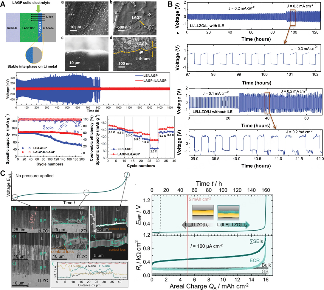
Figure 7. (A) Schematic diagram of the role of IL interlayer between bulk LAGP and Li along with SEM images at low-magnification (a) and high-magnification (b) and cross sectional SEM images in low-magnification (c) and high-magnification (d) of cycled Li anode with LAGP-ILE interlayer. Lithium stripping/plating analysis showing interfacial stability of bulk LAGP pellet and Li anode with the presence of IL, and charge-discharge performance and rate capability of solid-state Li|LAGP |LiFePO4 full cells with and without ILE interlayer. This figure is quoted with permission from Xiong et al.[148]. (B) Li stripping/plating voltage profiles of symmetric Li|LLZO|Li cells with and without ILE conducted at 25 °C. This figure is quoted with permission from Pervez et al. This figure is quoted with permission from
ISE and IL/ILE used for QSSEs, and their composition, ionic conductivity, and performance of QSSLMBs in terms of
| Materials | Conductivity (S cm-1) | Performance of QSSLMB | Ref. | |||||
| ISE family | IL or ILE | ISE:IL(E) in weight | r.t. | 60 °C | Cathode | Cycle speed | Q | |
| LLZOa) | [Py14][TFSI]/LiTFSI (19:1 wt/wt) | 80:20 | 4.0 × 10⁻⁴ | 1.6 × 10⁻³ | LiCoO2 | 0.1C | 140 | [145] |
| LLZOc) | FSI ILe) | 75:15 | 4.8 × 10⁻⁴c) | 2.1 × 10⁻³ | LiFePO4 | 0.05C | > 100 | [146] |
| DFOB ILf) | 75:15 | 1.9 × 10⁻⁴c) | 1.0 × 10⁻³ | - | - | [146] | ||
| LLZOb) | [Py14][TFSI] | 86:14 | 6.7 × 10⁻⁴ | ~3 × 10⁻³ | NMC811g) | 0.1C | 187 | [147] |
| LiFePO4 | 0.1C | ~150 | [147] | |||||
| LAGPd) | [Bmim][FSI]/LiFSI (9:1) | 50:50 | ~2 × 10⁻³ | ~5 × 10⁻³ | -h) | -h) | -h) | [148] |
ISE and ILE-based interlayer for QSSEs, treatment condition of ISE with ILE, and the performance of QSSLMBs in terms of
| Materials | Treatment method | Performance of QSSLMB | Ref. | ||||
| ISE family | ILE interlayer | Amount of ILE and treated side | Size of ISE (mm) | Cathode | Cycle speed | Q | |
| LAGPa) | [Bmim][FSI]/LiFSI (9:1) +LAGP 1:1 mixture | 8 mg on each side | - | LiFePO4 | 0.3C | ~140 | [148] |
| 2C | > 110 | [148] | |||||
| LSPSb) | 1.5 M LiTFSI in [Py13][TFSI] | 10 mg on Li surface and inside cathodee) | 10 | LiFePO4 | 0.1C | 144 | [149] |
| LLZOc) | LiTFSI - [Py14][FSI] (2:8 in mol) | < 1 µL on Li side and ~2 µL on cathode side | - | LiFePO4 | 20 mA g-1 | 145 | [150] |
| LGPSd) | [Li(triglyme)][TFSI] 75:15 | A drop on Li surface and 5 wt% in sulphur cathode | 16 | Sulphur | 0.2C | 1100 | [151] |
It is also possible to use ILE as an interlayer on or in electrodes. Basile et al. reported a facile SEI formation via a chemical interaction between Li metal anodes and [Py13][FSI] containing different lithium salts as the ILE for applications in LMBs. Symmetrical Li|ILE|Li cells cycled at 0.1 and 1.0 mA cm-2 displayed stable Li stripping/plating voltage profiles upon extended cycling (2,500 h) without any evidence of dendrite formation. Full Li|ILE|LiFePO4 cells displayed safe cycling at 1C rate, achieving 1,000 cycles with a Coulombic efficiency greater than 99.5%[149]. Taking this into account, ILEs, like LE, are expected to effectively improve the wettability between ISEs and Li and provide the building blocks to form a stable SEI and suppress Li dendrite formation.
When ILE is used as the interlayer material, it is generally applied over ISE on Li anode, while on the cathode side, it can be applied over or mixed in the cathode. Zheng et al. demonstrated an improved stability of the Li|LSPS interface by using a small amount of 1.5 M LiTFSI in [Pyr13][TFSI], which led to the formation of a stable SEI layer rather than the MCI formed when LSPS is in direct contact with Li. The ILE thin layers applied over the Li anode and also mixed in LiFePO4 provided a uniform ionic conductivity through the electrolyte/electrode interfaces, compensating for poor mechanical contact arising upon cycling. As a result, the QSSE-based Li|LiFePO4 cell showed a higher initial discharge capacity
Pervez et al. employed a QSSE consisting of thin [Pyr14][FSI]-LiTFSI interlayers on both sides of sintered LLZO pellets, which resulted in strongly reduced interfacial resistances at both the cathode and anode interfaces without the need for external pressure application. Furthermore, the ILE interlayer suppressed Li dendrite growth at current densities as high as 0.3 mA cm-2 [Figure 7B] via a more uniform Li flux through the interface. Li|LiFePO4 cells employing LLZO with ILE interlayers delivered reversible capacities as high as 145 mAh g-1 after five cycles and at a current density of 20 mA g(LFP)-1 at 25 °C with a Coulombic efficiency of around 100%. At elevated current densities of 40, 60, 80, and 100 mA g(LFP)-1, the cell delivered discharge capacities of ≈136, 125, 117, and 112 mAh g-1, respectively. Switching back to 20 mA g(LFP)-1, the initial capacity (≈145 mAh g(LFP)-1) was recovered and maintained till the 70th cycle. Compared to cells with liquid electrolytes, QSSLMBs are unique due to the fact that it is possible to assemble the cells in multi-polar stacked configuration, which leads to a higher output voltage and, thus, a higher volumetric energy density. As a proof-of-concept, the authors assembled series stacked cells, namely Li|LLZO|LFP-SS-Li|LLZO|LFP. The series stacked cells (OCV > 8 V) were also shown to deliver a high reversible capacity of ≈145 mAh g-1 with charge/discharge plateaus at potentials of 6.9 and 6.8 V vs. Li+/Li, indicating that the thin ILE interlayers were confined at the interfaces[150].
In a follow-up study, Fuchs et al. demonstrated the ILE to act as a “self-adjusting” interlayer alleviating the morphological changes of Li anode, enhancing the areal charge capacity for lithium stripping
Solvate ILs, which consist of a coordinating solvent (e.g., tetraglyme) and salt (e.g., LiTFSI), are also useful additives for QSSLMBs. Cao et al. investigated the combination of the [Li(triglyme)][TFSI] (LiG3) complex with LGPS discovering that the stabilised Li|LGPS interface was achieved through the formation of a SEI layer by the in situ electrochemical reduction of LiG3 complex on Li. The LiG3 complex incorporated at the Li|LGPS interface was fundamental in regulating Li+ transfer and suppressing the interfacial side reactions. The Li-S battery with such a QSSE exhibited improved electrochemical performance at room temperature, delivering 1,100 mAh g-1 at 0.2C rate and superior cyclic stability even at 1C rate[151].
Polymer-liquid-inorganic QSSEs
Sintered ISE pellets offer high ionic conductivities (10-4 to 10-3 Scm-1) but are intrinsically brittle, entailing poor contact with the electrodes including Li. This problem occurs especially on cycling when the electrode volume changes, leading to high interfacial impedance and eventual battery failure. Additionally, they cannot be easily adapted to the roll-to-roll production processes needed for large-volume production (such as for EVs).
An interesting approach to tackle these issues is to introduce Li-ion conducting polymer electrolytes (PEs), including both SPE and gel polymer electrolytes, as a matrix for ISE to form QSSEs and/or as a layer at the Li|SSE interface. Because of their flexible and cohesive nature, PEs can further improve the interfacial contact and mechanical stability of QSSEs. Inspired by the soft nature, high ionic conductivity, and better wettability offered by the polymer, numerous studies have reported on their use as QSSE in combination with ISEs, electrode binders, and electrode/electrolyte interlayers, with and without the further incorporation of LEs and ILEs.
Liu et al. used poly(vinylidenefluoride-co-hexafluoropropylene) (PVDF-HFP)-LE composite as interlayers between Li7La2.75Ca0.25Zr1.75Nb0.25O12 (LLCZNO) and electrodes to decrease the interfacial resistances against both the cathode and Li. Because of the presence of the PE interlayer, the interfacial resistance of LLCZNO decreases from 6.5 × 10⁴ to 248 Ω cm2 against the cathode and from 1.4 × 10³ to 214 Ω cm2 against Li. Furthermore, the full cell consisting of Li, the ISE with the interlayers, and LiFePO4 demonstrated a high capacity of around 140 mAh g-1 at 1C rate and stable cycling performance over 70 cycles. The results indicate that the PE layer can protect Li metal from the formation of a highly resistive interface, thus extending the cycle life of the QSSLMB[154].
Non-volatile, ILE-polymer-ISE QSSEs have also been explored, using either PEO or PVDF-HFP as matrices
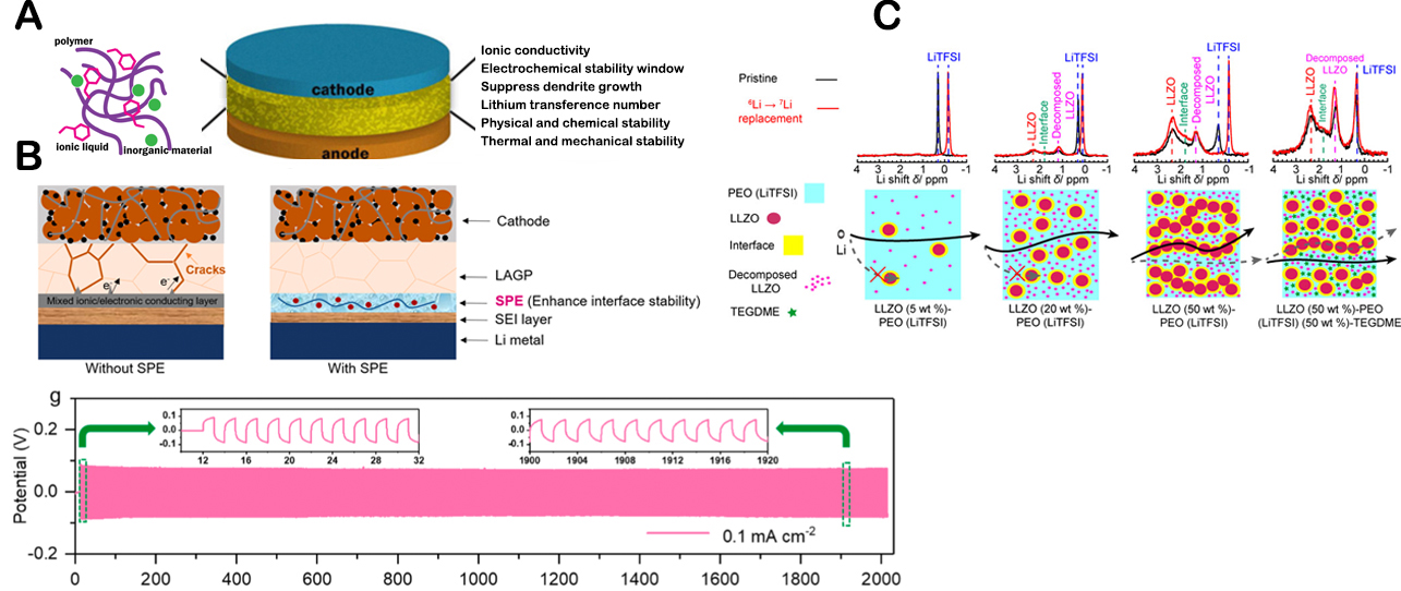
Figure 8. (A) Scheme of ILs containing polymer/inorganic hybrid electrolytes and key properties to study and improve. This figure is quoted with permission from Yang et al.[155]. (B) Schematic illustration of Li|LAGP|NCM811 QSSB without and with the SPE interlayer (top), Ultra-long-term galvanostatic stripping/plating experiment for Li|ILE/SPE/LAGP/SPE/ILE|Li cells with a constant current density of 0.1 mA cm-2. (bottom) (This figure is quoted with permission from Wu et al[158]. (C) Schematic of Li+ pathways within LLZO (5 (5, 20, and 50 wt.%)-)-PEO (LiTFSI), and LLZO (50 wt.%)-PEO (LiTFSI) (50 wt.%)-TEGDME composite electrolytes. Li NMR comparison of pristine and cycled LLZO (5, 20, and 50 wt.%) and LLZO (50 wt.%)-PEO (LiTFSI) (50 wt.%)-TEGDME. Reprinted (adapted) with permission from Zheng et al.[159]. Copyright (2018) American Chemical Society.
Recently, Wu et al. have designed a bilayer SSE architecture implementing a novel ultrathin (≤ 20 μm) PE film in combination with LAGP to improve the interfacial stability with Li. The PE film was composed of PEO cross-linked with benzophenone (BP) and a FSI-based IL, which showed a remarkable ionic conductivity of 1.25 × 10⁻³ S cm- 1 at room temperature. The presence of this thin interlayer led to outstanding interface stability for more than 2,000 h of continuous Li plating/stripping cycles in symmetric Li|SP/LAGP/SP|Li cells, allowing the realisation of high-energy QSSLMBs with long cycle life
Zheng et al. studied the ion mobility, ion transport pathways, and active ion concentration in LLZO dispersed in PEO-LiTFSI-tetraethylene glycol dimethyl ether (TEGDME) film, with different LLZO and TEGDME loadings, by means of solid-state nuclear magnetic resonance (NMR). The results showed that by increasing the fraction of LLZO, the Li+-ion mobility decreases because ion transport pathways change from one through the polymer region to one through the ceramic region, although the active ion concentration increases. It was also reported that a higher content of LLZO led to improved electrochemical stability of the QSSEs. On the contrary, the addition of TEGDME, forming LiTFSI-TGDME solvate IL in the composite, altered the ion transport pathways from the ceramic to the polymer route, increasing the ion mobility and enhancing ionic conductivity significantly even at high concentration of LLZO. These findings provide insight into the compositional dependence of ionic conductivity in current composite electrolytes and the intrinsic limitations of composite electrolytes in achieving fast ion conduction [Figure 8C][159].
Cheng et al. proposed a thin and flexible QSSE comprised of NASICON-type LATP [Li1+xAlxTi2-x(PO4)3] and poly(vinylidene fluoride-trifluorethylene) (PVDF-TrFE) incorporated with ILE to reinforce the interfacial electrochemical stability against Li[160,161]. Additionally, an ultrathin poly[2,3-bis(2,2,6,6-tetramethylpiperidine-N-oxycarbonyl)-norbornene] (PTNB) polymer was coated on Li, acting as a protective layer between QSSE and Li, to enable more uniform distribution of Li+ flux at the Li|QSSE interface, suppressing the Li dendrites growth. Especially when 0.3LiFSI-0.35[Pyr14][FSI]-0.35[Pyr14][TFSI] was used as ILE, the QSSE allowed Li|LiNi0.8Co0.1Mn0.1O2 cell to cycle over 500 cycles at 0.5C (131 mAh g-1 at the 500th cycle). Moreover, the proposed systems are confirmed as safer and more efficient than the solely oxide-based ISEs following experiments using intentionally damaged (rolled or cut) pouch cells. This highlights the strength of polymer matrices that can enhance the interfacial stability with the electrode and outstanding mechanical stability that cannot be achieved by ILEs.
CONCLUSIONS AND OUTLOOK
SSLMBs based on ISE are promising candidates for the next-generation rechargeable lithium batteries by virtue of their safety benefits, energy density, as well as unique mechanical and thermal stabilities. Significant research efforts in terms of the ionic conductivity of ISE have been made to deliver this technology commercially in the mass energy market. However, attaining operational SSEs remains a standing challenge due to the difficulty in forming an optimised Li|ISE interface offering fast Li+-ion transport for efficient cell operation and in minimising electronic conductivity to avoid the continuous degradation of the cell components and performance. Additionally, the Li dendrite growth occurring at Li|ISE interface, which relates to the electronic conductivity and also crystalline nature of ISE, remains the main limitation that has yet to be resolved.
To solve these issues and realise ideal interfaces, the main challenges include: (1) the improvement of electrochemical stability of ISE; and (2) the formation of ISE with low boundary resistances not only at ISE grains but also at electrode grains. Although oxide-based ISEs possess generally good electrochemical stability with Li metal, the poor Li|ISE interface contact induces the formation of Li dendrites rapidly propagating at the grain boundaries, surface defects and interconnected pores of ISEs. While improvement of inherent properties of ISEs has been intensively studied, it is also possible to improve their properties by adding secondary materials, such as LE, ILE, and SP, to form QSSE.
As summarised in this review, QSSEs synergistically combine the advantages of ISE and LEs, offering improved safety, durability, and electrochemical performance. The addition of infiltration materials to ISEs can improve the poor Li-ISE contact and sluggish interfacial kinetics by infiltrating voids among ISE particles, thus enhancing the overall performance of SSLBs. Among the three additives to form QSSE, i.e., LE, ILE, and SP, LE possess the highest ionic conductivity, yet its use should be limited in terms of amount to form QSSEs so as to not impede the safety advantage of ISEs. For advanced battery systems, QSSEs containing ILEs or PE would be favourable. As of today, only a limited number of ILEs have been tested as interlayer or infiltrating material for ISEs because high chemical and electrochemical stabilities are required for battery application and also for compatibility with ISEs. However, taking the numerous structural possibilities of ILEs into consideration, it should be possible to design task-specific ILEs for QSSEs. For example, several ILs based on oxalatoborate are known to form a protective layer on the cathode side. For Na-ion batteries, the use of sacrificial salts has been proposed to be favourable for stable battery performance. Similarly, it should be possible to synthesise ILE with the ability to form a protective layer during battery cycling. In addition, the optimised amount of ILEs added to ISEs has not yet been defined. This is because the value should depend on various factors such as (1) compatibility between ILs and ISEs to suppress the leakage of ILs; (2) particle size of ISEs and surface area to be treated (pellets or powders); and (3) viscosity of ILs; hence, further systematic analyses must be carried out.
The use of polymer matrices in QSSEs is an effective means to enhance the flexibility of electrolytes, which would be more advantageous for industrial purposes not only in terms of better scalability of their production but also improved safety of final battery products, as confirmed by Cheng et al.[160,161]. Currently, the production of functional SSBs requires a high-temperature sintering process of ISEs and specific cell design allowing external pressure application, both of which lead to an increase in the cost of batteries. By using PE based on flexible polymer matrices, the scalability of material production, especially with seamless contact among the battery components, is expected to be improved. By using solely inorganic compounds, enhancement of mechanical stability is difficult. In contrast, the combination of organic and inorganic materials in QSSEs allows the design of flexible materials, which can be folded, cut, and wearable; these advantages are important for the implementation of QSSEs in commercial applications. So far, a limited number of ILE or PE for QSSE have been tested; hence, advancements in the design of novel and cost-effective QSSE are anticipated.
DECLARATIONS
AcknowledgementsHenry Adenusi acknowledges the Hong Kong Quantum AI Lab Limited, AIR@InnoHK of the Hong Kong government for supporting his fellowship.
Authors’ contributionsProposed the topic of this review: Passerini S
Prepared the manuscript: Mazzapioda L
Collectively discussed and revised the manuscript: Mazzapioda L, Tsurumaki A, Di Donato G, Adenusi H, Navarra MA, Passerini S
Financial support and sponsorshipThis work was supported by the Helmholtz Association.
Conflicts of interestAll authors declared that there are no conflicts of interest.
Ethical approval and consent to participateNot applicable.
Consent for publicationNot applicable.
Copyright©TheAuthor(s) 2023.
REFERENCES
1. Scrosati B, Garche J. Lithium batteries: status, prospects and future. J Power Sources 2010;195:2419-30.
3. Passerini S, Scrosati B. Lithium and lithium-ion batteries: challenges and prospects. Electrochem Soc Interface 2016;25:85-7.
4. Kalhoff J, Eshetu GG, Bresser D, Passerini S. Safer electrolytes for lithium-ion batteries: state of the art and perspectives. ChemSusChem 2015;8:2154-75.
5. Chen Y, Kang Y, Zhao Y, et al. A review of lithium-ion battery safety concerns: the issues, strategies, and testing standards. J Energy Chem 2021;59:83-99.
6. Xu W, Wang J, Ding F, et al. Lithium metal anodes for rechargeable batteries. Energy Environ Sci 2014;7:513-37.
7. Wang H, Yu D, Kuang C, et al. Alkali metal anodes for rechargeable batteries. Chem 2019;5:313-38.
8. Adenusi H, Chass GA, Passerini S, Tian KV, Chen G. Lithium batteries and the solid electrolyte interphase (SEI) - progress and outlook. Adv Energy Mater 2023;13:2203307.
9. Jha V, Krishnamurthy B. Modeling the SEI layer formation and its growth in lithium-ion batteries (LiB) during charge-discharge cycling. Ionics 2022;28:3661-70.
10. Lewis JA, Tippens J, Cortes FJQ, Mcdowell MT. Chemo-mechanical challenges in solid-state batteries. Trends Chem 2019;1:845-57.
11. Donato G, Ates T, Adenusi H, Varzi A, Navarra MA, Passerini S. Electrolyte measures to prevent polysulfide shuttle in lithium-sulfur batteries. Batteries Supercaps 2022;5:e202200097-121.
12. Fergus JW. Ceramic and polymeric solid electrolytes for lithium-ion batteries. J Power Sources 2010;195:4554-69.
13. Sashmitha K, Rani MU. A comprehensive review of polymer electrolyte for lithium-ion battery. Polym Bull 2023;80:89-135.
14. Mindemark J, Lacey MJ, Bowden T, Brandell D. Beyond PEO - alternative host materials for Li+-conducting solid polymer electrolytes. Prog Polym Sci 2018;81:114-43.
15. Alexander GV, Patra S, Sobhan Raj SV, Sugumar MK, Ud Din MM, Murugan R. Electrodes-electrolyte interfacial engineering for realizing room temperature lithium metal battery based on garnet structured solid fast Li+ conductors. J Power Sources 2018;396:764-73.
16. Chen R, Nolan AM, Lu J, et al. The thermal stability of lithium solid electrolytes with metallic lithium. Joule 2020;4:812-21.
17. Schwietert TK, Vasileiadis A, Wagemaker M. First-principles prediction of the electrochemical stability and reaction mechanisms of solid-state electrolytes. JACS Au 2021;1:1488-96.
18. Manthiram A, Yu X, Wang S. Lithium battery chemistries enabled by solid-state electrolytes. Nat Rev Mater 2017;2:16103.
19. Wei R, Chen S, Gao T, Liu W. Challenges, fabrications and horizons of oxide solid electrolytes for solid-state lithium batteries. Nano Select 2021;2:2256-74.
20. Zhao Q, Stalin S, Zhao C, Archer LA. Designing solid-state electrolytes for safe, energy-dense batteries. Nat Rev Mater 2020;5:229-52.
21. Gurung A, Pokharel J, Baniya A, et al. A review on strategies addressing interface incompatibilities in inorganic all-solid-state lithium batteries. Sustain Energy Fuels 2019;3:3279-309.
22. Fan L, Wei S, Li S, Li Q, Lu Y. Recent progress of the solid-state electrolytes for high-energy metal-based batteries. Adv Energy Mater 2018;8:1702657.
23. Lu J, Li Y. Perovskite-type Li-ion solid electrolytes: a review. J Mater Sci Mater Electron 2021;32:9736-54.
24. Ramakumar S, Deviannapoorani C, Dhivya L, Shankar LS, Murugan R. Lithium garnets: synthesis, structure, Li+ conductivity, Li+ dynamics and applications. Prog Mater Sci 2017;88:325-411.
25. Wang P, Qu W, Song W, Chen H, Chen R, Fang D. Electro-Chemo-Mechanical issues at the interfaces in solid-state lithium metal batteries. Adv Funct Mater 2019;29:1900950-79.
26. Lim H, Park J, Shin H, et al. A review of challenges and issues concerning interfaces for all-solid-state batteries. Energy Stor Mater 2020;25:224-50.
27. Tsurumaki A, Ohno H. Dissolution of oligo(tetrafluoroethylene) and preparation of poly(tetrafluoroethylene)-based composites by using fluorinated ionic liquids. Chem Commun 2018;54:409-12.
28. Kalhoff J, Kim G, Passerini S, Appetecchi GB. Safety assessment of ionic liquid-based lithium-ion battery prototypes. J Energy Power Eng 2016;04:9-18.
29. Shin J. Ionic liquids to the rescue? overcoming the ionic conductivity limitations of polymer electrolytes. Electrochem Commun 2003;5:1016-20.
30. Tian L, Wang M, Liu Y, et al. Multiple ionic conduction highways and good interfacial stability of ionic liquid-encapsulated cross-linked polymer electrolytes for lithium metal batteries. J Power Sources 2022;543:231848.
31. Eshetu G, Armand M, Scrosati B, Passerini S. Energy storage materials synthesized from ionic liquids. Angew Chem Int Ed 2014;53:13342-59.
32. Osada I, de Vries H, Scrosati B, Passerini S. Ionic-liquid-based polymer electrolytes for battery applications. Angew Chem Int Ed 2016;55:500-13.
33. Ito S, Unemoto A, Ogawa H, Tomai T, Honma I. Application of quasi-solid-state silica nanoparticles-ionic liquid composite electrolytes to all-solid-state lithium secondary battery. J Power Sources 2012;208:271-5.
34. Wen Z, Li Y, Zhao Z, et al. A leaf-like Al2O3-based quasi-solid electrolyte with a fast Li+ conductive interface for stable lithium metal anodes. J Mater Chem A 2020;8:7280-7.
35. Liu S, Liu W, Ba D, et al. Filler-integrated composite polymer electrolyte for solid-state lithium batteries. Adv Mater 2023;35:e2110423.
36. Huy VP, So S, Hur J. Inorganic fillers in composite gel polymer electrolytes for high-performance lithium and non-lithium polymer batteries. Nanomaterials 2021;11:614.
37. Chen R, Li Q, Yu X, Chen L, Li H. Approaching practically accessible solid-state batteries: stability issues related to solid electrolytes and interfaces. Chem Rev 2020;120:6820-77.
41. Wang C, Fu K, Kammampata SP, et al. Garnet-type solid-state electrolytes: materials, interfaces, and batteries. Chem Rev 2020;120:4257-300.
42. Goodenough J, Hong H, Kafalas J. Fast Na+-ion transport in skeleton structures. Mater Res Bull 1976;11:203-20.
43. Wells AF. Structural inorganic chemistry, 4th ed. Oxford: Clarendon Press; 1975.
44. Thangadurai V, Weppner W. Li6ALa2Ta2O12 (A = Ca, Sr, Ba): A new class of fast lithium ion conductors with garnet-like structure. J Am Ceram Soc 2005;88:411-8.
45. Thangadurai V, Weppner W. Li6ALa2Ta2O12 (A = Sr, Ba): novel Garnet-like oxides for fast lithium ion conduction. Adv Funct Mater 2005;15:107-12.
46. Thangadurai V, Narayanan S, Pinzaru D. Garnet-type solid-state fast Li ion conductors for Li batteries: critical review. Chem Soc Rev 2014;43:4714-27.
47. Murugan R, Thangadurai V, Weppner W. Fast lithium ion conduction in garnet-type Li7La3Zr2O12. Angew Chem Int Ed 2007;46:7778-81.
48. Wang W, Wang X, Gao Y, Fang Q. Lithium-ionic diffusion and electrical conduction in the Li7La3Ta2O13 compounds. Solid State Ion 2009;180:1252-6.
49. Mariappan CR, Gnanasekar KI, Jayaraman V, Gnanasekaran T. Lithium ion conduction in Li5La3Ta2O12 and Li7La3Ta2O13 garnet-type materials. J Electroceram 2013;30:258-65.
50. Cussen EJ. The structure of lithium garnets: cation disorder and clustering in a new family of fast Li+ conductors. Chem Commun 2006:412-3.
51. Wu JF, Pang WK, Peterson VK, Wei L, Guo X. Garnet-type fast Li-ion conductors with high ionic conductivities for all-solid-state batteries. ACS Appl Mater Interfaces 2017;9:12461-8.
52. Xia W, Xu B, Duan H, et al. Ionic conductivity and air stability of Al-doped Li7La3Zr2O12 sintered in alumina and Pt crucibles. ACS Appl Mater Interfaces 2016;8:5335-42.
53. Sharafi A, Yu S, Naguib M, et al. Impact of air exposure and surface chemistry on Li-Li7La3Zr2O12 interfacial resistance. J Mater Chem A 2017;5:13475-87.
54. Sun Y, Guan P, Liu Y, Xu H, Li S, Chu D. Recent progress in lithium lanthanum titanate electrolyte towards all solid-state lithium ion secondary battery. Crit Rev Solid State 2019;44:265-82.
55. Stramare S, Thangadurai V, Weppner W. Lithium lanthanum titanates: a review. Chem Mater 2003;15:3974-90.
56. Inaguma Y, Liquan C, Itoh M, et al. High ionic conductivity in lithium lanthanum titanate. Solid State Commun 1993;86:689-93.
57. Yan S, Yim C, Pankov V, et al. Perovskite solid-state electrolytes for lithium metal batteries. Batteries 2021;7:75.
58. Chen C. Ionic conductivity, lithium insertion and extraction of lanthanum lithium titanate. Solid State Ion 2001;144:51-7.
59. Hong H. Crystal structure and ionic conductivity of Li14Zn(GeO4)4 and other new Li+ superionic conductors. Mater Res Bull 1978;13:117-24.
61. Shannon R, Taylor B, English A, Berzins T. New Li solid electrolytes. Electrochim Acta 1977;22:783-96.
62. Hu Y, Raistrick ID, Huggins RA. Ionic conductivity of lithium orthosilicate - lithium phosphate solid solutions. J Electrochem Soc 1977;124:1240-2.
63. Lau J, Deblock RH, Butts DM, Ashby DS, Choi CS, Dunn BS. Sulfide solid electrolytes for lithium battery applications. Adv Energy Mater 2018;8:1800933.
64. Yu X, Bates JB, Jellison GE, Hart FX. A stable thin-film lithium electrolyte: lithium phosphorus oxynitride. J Electrochem Soc 1997;144:524-32.
65. Oudenhoven JFM, Baggetto L, Notten PHL. All-solid-state lithium-ion microbatteries: a review of various three-dimensional concepts. Adv Energy Mater 2011;1:10-33.
66. Nowak S, Berkemeier F, Schmitz G. Ultra-thin LiPON films - fundamental properties and application in solid state thin film model batteries. J Power Sources 2015;275:144-50.
67. Bates J, Dudney N, Gruzalski G, et al. Fabrication and characterization of amorphous lithium electrolyte thin films and rechargeable thin-film batteries. J Power Sources 1993;43:103-10.
68. Cheng D, Wynn TA, Wang X, et al. Unveiling the stable nature of the solid electrolyte interphase between lithium metal and LiPON via cryogenic electron microscopy. Joule 2020;4:2484-500.
69. López-aranguren P, Reynaud M, Głuchowski P, et al. Crystalline LiPON as a bulk-type solid electrolyte. ACS Energy Lett 2021;6:445-50.
70. Zhang X, Temeche E, Laine RM. Design, synthesis, and characterization of polymer precursors to Li
71. Lee S, Bae J, Lee H, Baik H, Lee S. Electrical conductivity in Li-Si-P-O-N oxynitride thin-films. J Power Sources 2003;123:61-4.
72. Su Y, Falgenhauer J, Leichtweiß T, et al. Electrochemical properties and optical transmission of high Li+ conducting LiSiPON electrolyte films: electrochemical properties of high Li+ conducting LiSiPON electrolyte films. Phys Status Solidi B 2017;254:1600088.
73. Wang W, Jiang B, Hu L, Jiao S. Nasicon material NaZr2(PO4)3: a novel storage material for sodium-ion batteries. J Mater Chem A 2014;2:1341-5.
74. Zhao D, Xie Z, Hu J, et al. Structure determination, electronic and optical properties of NaGe2P3O12 and Cs2GeP4O13. J Molecular Struct 2009;922:127-34.
75. Ortiz-mosquera JF, Nieto-muñoz AM, Rodrigues AC. Precursor glass stability, microstructure and ionic conductivity of glass-ceramics from the Na1+xAlxGe2-x(PO4)3 NASICON series. J Non-Cryst Solids 2019;513:36-43.
76. Wu M, Ni W, Hu J, Ma J. NASICON-structured NaTi2(PO4)3 for sustainable energy storage. Nano-Micro Lett 2019;11:44.
77. Bachman JC, Muy S, Grimaud A, et al. Inorganic solid-state electrolytes for lithium batteries: mechanisms and properties governing ion conduction. Chem Rev 2016;116:140-62.
78. Tan G, Wu F, Li L, Liu Y, Chen R. Magnetron sputtering preparation of nitrogen-incorporated lithium-aluminum-titanium phosphate based thin film electrolytes for all-solid-state lithium ion batteries. J Phys Chem C 2012;116:3817-26.
79. Illbeigi M, Fazlali A, Kazazi M, Mohammadi AH. Effect of simultaneous addition of aluminum and chromium on the lithium ionic conductivity of LiGe2(PO4)3 NASICON-type glass-ceramics. Solid State Ion 2016;289:180-7.
81. Mo Y, Ong SP, Ceder G. First principles study of the Li10GeP2S12 lithium super ionic conductor material. Chem Mater 2012;24:15-7.
82. Adams S, Prasada Rao R. Structural requirements for fast lithium ion migration in Li10GeP2S12. J Mater Chem 2012;22:7687.
83. Hu C, Wang Z, Sun Z, Ouyang C. Insights into structural stability and Li superionic conductivity of Li10GeP2S12 from first-principles calculations. Chem Phys Lett 2014;591:16-20.
84. Chen S, Xie D, Liu G, et al. Sulfide solid electrolytes for all-solid-state lithium batteries: structure, conductivity, stability and application. Energy Stor Mater 2018;14:58-74.
85. Dietrich C, Weber DA, Sedlmaier SJ, et al. Lithium ion conductivity in Li2S-P2S5 glasses - building units and local structure evolution during the crystallization of superionic conductors Li3PS4, Li7P3S11 and Li4P2S7. J Mater Chem A 2017;5:18111-9.
86. Wang G, Lin C, Gao C, et al. Hydrolysis-resistant and anti-dendritic halide composite Li3PS4-LiI solid electrolyte for all-solid-state lithium batteries. Electrochim Acta 2022;428:140906.
87. Calpa M, Rosero-navarro NC, Miura A, Jalem R, Tateyama Y, Tadanaga K. Chemical stability of Li4PS4I solid electrolyte against hydrolysis. Appl Mater Today 2021;22:100918.
88. Rao RP, Adams S. Studies of lithium argyrodite solid electrolytes for all-solid-state batteries: studies of lithium argyrodite solid electrolytes. Phys Status Solidi A 2011;208:1804-7.
89. Boulineau S, Courty M, Tarascon J, Viallet V. Mechanochemical synthesis of Li-argyrodite Li6PS5X (X = Cl, Br, I) as sulfur-based solid electrolytes for all solid state batteries application. Solid State Ion 2012;221:1-5.
90. Deiseroth H, Maier J, Weichert K, Nickel V, Kong S, Reiner C. Li7PS6 and Li6PS5X (X: Cl, Br, I): possible three-dimensional diffusion pathways for lithium ions and temperature dependence of the ionic conductivity by impedance measurements. Z Anorg Allg Chem 2011;637:1287-94.
91. Deiseroth HJ, Kong ST, Eckert H, et al. Li6PS5X: a class of crystalline Li-rich solids with an unusually high Li+ mobility. Angew Chem Int Ed 2008;47:755-8.
92. Zhu Y, He X, Mo Y. First principles study on electrochemical and chemical stability of solid electrolyte-electrode interfaces in all-solid-state Li-ion batteries. J Mater Chem A 2016;4:3253-66.
93. Wang S, Wu Y, Ma T, Chen L, Li H, Wu F. Thermal stability between sulfide solid electrolytes and oxide cathode. ACS Nano 2022;16:16158-76.
94. Paul PP, Chen B, Langevin SA, Dufek EJ, Nelson Weker J, Ko JS. Interfaces in all solid state Li-metal batteries: a review on instabilities, stabilization strategies, and scalability. Energy Stor Mater 2022;45:969-1001.
95. Pervez SA, Cambaz MA, Thangadurai V, Fichtner M. Interface in solid-state lithium battery: challenges, progress, and outlook. ACS Appl Mater Interfaces 2019;11:22029-50.
97. Banerjee A, Wang X, Fang C, Wu EA, Meng YS. Interfaces and interphases in all-solid-state batteries with inorganic solid electrolytes. Chem Rev 2020;120:6878-933.
98. Wenzel S, Leichtweiss T, Krüger D, Sann J, Janek J. Interphase formation on lithium solid electrolytes - an
99. Zhu Y, He X, Mo Y. Origin of outstanding stability in the lithium solid electrolyte materials: insights from thermodynamic analyses based on first-principles calculations. ACS Appl Mater Interfaces 2015;7:23685-93.
100. Wenzel S, Weber DA, Leichtweiss T, Busche MR, Sann J, Janek J. Interphase formation and degradation of charge transfer kinetics between a lithium metal anode and highly crystalline Li7P3S11 solid electrolyte. Solid State Ion 2016;286:24-33.
101. Wenzel S, Randau S, Leichtweiß T, et al. Direct observation of the interfacial instability of the fast ionic conductor Li10GeP2S12 at the lithium metal anode. Chem Mater 2016;28:2400-7.
102. Cheng L, Crumlin EJ, Chen W, et al. The origin of high electrolyte-electrode interfacial resistances in lithium cells containing garnet type solid electrolytes. Phys Chem Chem Phys 2014;16:18294-300.
103. Aatiq A, Ménétrier M, Croguennec L, Suard E, Delmas C. On the structure of Li3Ti2(PO4)3. J Mater Chem 2002;12:2971-8.
104. Ma C, Cheng Y, Yin K, et al. Interfacial stability of Li metal-solid electrolyte elucidated via
105. Zhu Y, Connell JG, Tepavcevic S, et al. Dopant-dependent stability of garnet solid electrolyte interfaces with lithium metal. Adv Energy Mater 2019;9:1803440.
106. Hartmann P, Leichtweiss T, Busche MR, et al. Degradation of NASICON-type materials in contact with lithium metal: formation of mixed conducting interphases (MCI) on solid electrolytes. J Phys Chem C 2013;117:21064-74.
107. Tolganbek N, Serikkazyyeva A, Kalybekkyzy S, et al. Interface modification of NASICON-type Li-ion conducting ceramic electrolytes: a critical evaluation. Mater Adv 2022;3:3055-69.
108. Schwöbel A, Hausbrand R, Jaegermann W. Interface reactions between LiPON and lithium studied by
109. Han X, Gong Y, Fu KK, et al. Negating interfacial impedance in garnet-based solid-state Li metal batteries. Nat Mater 2017;16:572-9.
110. Sharafi A, Kazyak E, Davis AL, et al. Surface chemistry mechanism of ultra-low interfacial resistance in the solid-state electrolyte
111. Krauskopf T, Hartmann H, Zeier WG, Janek J. Toward a fundamental understanding of the lithium metal anode in solid-state batteries-an electrochemo-mechanical study on the garnet-type solid electrolyte Li6.25Al0.25La3Zr2O12. ACS Appl Mater Interfaces 2019;11:14463-77.
112. Liu T, Zhang Y, Chen R, et al. Non-successive degradation in bulk-type all-solid-state lithium battery with rigid interfacial contact. Electrochem Commun 2017;79:1-4.
113. Zhu J, Zhao J, Xiang Y, et al. Chemomechanical failure mechanism study in NASICON-type Li1.3Al0.3Ti1.7(PO4)3 solid-state lithium batteries. Chem Mater 2020;32:4998-5008.
114. Lee C, Han SY, Lewis JA, et al. Stack pressure measurements to probe the evolution of the lithium-solid-state electrolyte interface. ACS Energy Lett 2021;6:3261-9.
115. Tippens J, Miers JC, Afshar A, et al. Visualizing chemomechanical degradation of a solid-state battery electrolyte. ACS Energy Lett 2019;4:1475-83.
116. Yuan C, Lu W, Xu J. Unlocking the electrochemical-mechanical coupling behaviors of dendrite growth and crack propagation in all-solid-state batteries. Adv Energy Mater 2021;11:2101807.
117. Xu X, Liu Y, Kapitanova OO, Song Z, Sun J, Xiong S. Electro-Chemo-Mechanical failure of solid electrolytes induced by growth of internal lithium filaments. Adv Mater 2022;34:e2207232.
118. Cao D, Sun X, Li Q, Natan A, Xiang P, Zhu H. Lithium dendrite in all-solid-state batteries: growth mechanisms, suppression strategies, and characterizations. Matter 2020;3:57-94.
119. Monroe C, Newman J. The impact of elastic deformation on deposition kinetics at lithium/polymer interfaces. J Electrochem Soc 2005;152:A396.
120. Tsai CL, Roddatis V, Chandran CV, et al. Li7La3Zr2O12 interface modification for Li dendrite prevention. ACS Appl Mater Interfaces 2016;8:10617-26.
121. Xu B, Li W, Duan H, et al. Li3PO4-added garnet-type Li6.5La3Zr1.5Ta0.5O12 for Li-dendrite suppression. J Power Sources 2017;354:68-73.
122. Porz L, Swamy T, Sheldon BW, et al. Mechanism of lithium metal penetration through inorganic solid electrolytes. Adv Energy Mater 2017;7:1701003.
123. Shen F, Dixit MB, Xiao X, Hatzell KB. Effect of pore connectivity on Li dendrite propagation within LLZO electrolytes observed with synchrotron X-ray tomography. ACS Energy Lett 2018;3:1056-61.
124. Cheng EJ, Sharafi A, Sakamoto J. Intergranular Li metal propagation through polycrystalline Li6.25Al0.25La3Zr2O12 ceramic electrolyte. Electrochim Acta 2017;223:85-91.
125. Zheng C, Ruan Y, Su J, et al. Grain boundary modification in garnet electrolyte to suppress lithium dendrite growth. Chem Eng J 2021;411:128508.
126. Han F, Westover AS, Yue J, et al. High electronic conductivity as the origin of lithium dendrite formation within solid electrolytes. Nat Energy 2019;4:187-96.
127. Ping W, Wang C, Lin Z, et al. Reversible short-circuit behaviors in garnet-based solid-state batteries. Adv Energy Mater 2020;10:2000702.
128. Biao J, Han B, Cao Y, et al. Inhibiting formation and reduction of Li2CO3 to LiCx at grain boundaries in garnet electrolytes to prevent Li penetration. Adv Mater 2023;35:e2208951.
129. Huang X, Lu Y, Guo H, et al. None-mother-powder method to prepare dense Li-garnet solid electrolytes with high critical current density. ACS Appl Energy Mater 2018;1:5355-65.
130. Kazyak E, Garcia-mendez R, Lepage WS, et al. Li penetration in ceramic solid electrolytes: operando microscopy analysis of morphology, propagation, and reversibility. Matter 2020;2:1025-48.
131. Westover AS, Dudney NJ, Sacci RL, Kalnaus S. Deposition and confinement of Li metal along an artificial lipon-lipon interface. ACS Energy Lett 2019;4:651-5.
132. Lu Y, Tu Z, Archer LA. Stable lithium electrodeposition in liquid and nanoporous solid electrolytes. Nat Mater 2014;13:961-9.
133. Lv Y, Xiao Y, Ma L, Zhi C, Chen S. Recent advances in electrolytes for “beyond aqueous” zinc-ion batteries. Adv Mater 2022;34:e2106409.
134. Judez X, Martinez-ibañez M, Santiago A, Armand M, Zhang H, Li C. Quasi-solid-state electrolytes for lithium sulfur batteries: advances and perspectives. J Power Sources 2019;438:226985.
135. Busche MR, Drossel T, Leichtweiss T, et al. Dynamic formation of a solid-liquid electrolyte interphase and its consequences for hybrid-battery concepts. Nat Chem 2016;8:426-34.
136. Wang Q, Jin J, Wu X, Ma G, Yang J, Wen Z. A shuttle effect free lithium sulfur battery based on a hybrid electrolyte. Phys Chem Chem Phys 2014;16:21225-9.
137. Xu B, Duan H, Liu H, Wang CA, Zhong S. Stabilization of garnet/liquid electrolyte interface using superbase additives for hybrid Li batteries. ACS Appl Mater Interfaces 2017;9:21077-82.
138. Zhou H, Liu H, Li Y, et al.
139. Wang C, Sun Q, Liu Y, et al. Boosting the performance of lithium batteries with solid-liquid hybrid electrolytes: interfacial properties and effects of liquid electrolytes. Nano Energy 2018;48:35-43.
140. Nikodimos Y, Su W, Taklu BW, et al. Resolving anodic and cathodic interface-incompatibility in solid-state lithium metal battery via interface infiltration of designed liquid electrolytes. J Power Sources 2022;535:231425.
141. Yan S, Abouali S, Yim C, et al. Revealing the role of liquid electrolytes in cycling of garnet-based solid-state lithium-metal batteries. J Phys Chem C 2022;126:14027-35.
142. Tang J, Wang L, You L, et al. Effect of organic electrolyte on the performance of solid electrolyte for solid-liquid hybrid lithium batteries. ACS Appl Mater Interfaces 2021;13:2685-93.
143. Li J, Li F, Zhang L, Zhang H, Lassi U, Ji X. Recent applications of ionic liquids in quasi-solid-state lithium metal batteries. Green Chem Eng 2021;2:253-65.
144. Armand M, Endres F, MacFarlane DR, Ohno H, Scrosati B. Ionic-liquid materials for the electrochemical challenges of the future. Nat Mater 2009;8:621-9.
145. Kim HW, Manikandan P, Lim YJ, Kim JH, Nam SC, Kim Y. Hybrid solid electrolyte with the combination of Li7La3Zr2O12 ceramic and ionic liquid for high voltage pseudo-solid-state Li-ion batteries. J Mater Chem A 2016;4:17025-32.
146. Tsurumaki A, Rettaroli R, Mazzapioda L, Navarra MA. Inorganic-organic hybrid electrolytes based on Al-doped Li7La3Zr2O12 and ionic liquids. Appl Sci 2022;12:7318.
147. Zhang Z, Zhang L, Liu Y, et al. Interface-engineered Li7La3Zr2O12-based garnet solid electrolytes with suppressed Li-dendrite formation and enhanced electrochemical performance. ChemSusChem 2018;11:3774-82.
148. Xiong S, Liu Y, Jankowski P, et al. Design of a multifunctional interlayer for NASCION-based solid-state Li metal batteries. Adv Funct Mater 2020;30:2001444.
149. Basile A, Bhatt AI, O’Mullane AP. Stabilizing lithium metal using ionic liquids for long-lived batteries. Nat Commun 2016;7:ncomms11794.
150. Pervez SA, Kim G, Vinayan BP, et al. Overcoming the interfacial limitations imposed by the solid-solid interface in solid-state batteries using ionic liquid-based interlayers. Small 2020;16:e2000279.
151. Cao Y, Zuo P, Lou S, et al. A quasi-solid-state Li-S battery with high energy density, superior stability and safety. J Mater Chem A 2019;7:6533-42.
152. Zheng B, Zhu J, Wang H, et al. Stabilizing Li10SnP2S12/Li interface via an
153. Fuchs T, Mogwitz B, Otto S, Passerini S, Richter FH, Janek J. Working Principle of an ionic liquid interlayer during pressureless lithium stripping on Li6.25Al0.25La3Zr2O12 (LLZO) garnet-type solid electrolyte. Batteries Supercaps 2021;4:1145-55.
154. Liu B, Gong Y, Fu K, et al. Garnet solid electrolyte protected Li-metal batteries. ACS Appl Mater Interfaces 2017;9:18809-15.
155. Yang G, Song Y, Wang Q, Zhang L, Deng L. Review of ionic liquids containing, polymer/inorganic hybrid electrolytes for lithium metal batteries. Mater Des 2020;190:108563.
156. Fei H, Han J, Passerini S, Varzi A. Hybrid organic/inorganic interphase for stabilizing a zinc metal anode in a mild aqueous electrolyte. ACS Appl Mater Interfaces 2022;14:48675-81.
157. Huo H, Zhao N, Sun J, Du F, Li Y, Guo X. Composite electrolytes of polyethylene oxides/garnets interfacially wetted by ionic liquid for room-temperature solid-state lithium battery. J Power Sources 2017;372:1-7.
158. Wu F, Fang S, Kuenzel M, et al. Bilayer solid electrolyte enabling quasi-solid-state lithium-metal batteries. J Power Sources 2023;557:232514.
159. Zheng J, Hu YY. New insights into the compositional dependence of Li-ion transport in polymer-ceramic composite electrolytes. ACS Appl Mater Interfaces 2018;10:4113-20.
160. Chen Z, Stepien D, Wu F, et al. Stabilizing the Li1.3Al0.3Ti1.7(PO4)3|Li interface for high efficiency and long lifespan quasi-solid-state lithium metal batteries. ChemSusChem 2022;15:e202200038.
Cite This Article
Export citation file: BibTeX | RIS
OAE Style
Mazzapioda L, Tsurumaki A, Di Donato G, Adenusi H, Navarra MA, Passerini S. Quasi-solid-state electrolytes - strategy towards stabilising Li|inorganic solid electrolyte interfaces in solid-state Li metal batteries. Energy Mater 2023;3:300019. http://dx.doi.org/10.20517/energymater.2023.03
AMA Style
Mazzapioda L, Tsurumaki A, Di Donato G, Adenusi H, Navarra MA, Passerini S. Quasi-solid-state electrolytes - strategy towards stabilising Li|inorganic solid electrolyte interfaces in solid-state Li metal batteries. Energy Materials. 2023; 3(2): 300019. http://dx.doi.org/10.20517/energymater.2023.03
Chicago/Turabian Style
Mazzapioda, Lucia, Akiko Tsurumaki, Graziano Di Donato, Henry Adenusi, Maria Assunta Navarra, Stefano Passerini. 2023. "Quasi-solid-state electrolytes - strategy towards stabilising Li|inorganic solid electrolyte interfaces in solid-state Li metal batteries" Energy Materials. 3, no.2: 300019. http://dx.doi.org/10.20517/energymater.2023.03
ACS Style
Mazzapioda, L.; Tsurumaki A.; Di Donato G.; Adenusi H.; Navarra MA.; Passerini S. Quasi-solid-state electrolytes - strategy towards stabilising Li|inorganic solid electrolyte interfaces in solid-state Li metal batteries. Energy Mater. 2023, 3, 300019. http://dx.doi.org/10.20517/energymater.2023.03
About This Article
Special Issue
Copyright

Data & Comments
Data


 Cite This Article 25 clicks

 Like This Article 8
likes
Like This Article 8
likes


Comments
Comments must be written in English. Spam, offensive content, impersonation, and private information will not be permitted. If any comment is reported and identified as inappropriate content by OAE staff, the comment will be removed without notice. If you have any queries or need any help, please contact us at support@oaepublish.com.